Representation of Continuous & Discrete, Time Signals - 2 | Signals and Systems - Electrical Engineering (EE) PDF Download
Operations in Continous Time Signals:
Periodic & Non-Periodic Signals:
- A signal is a periodic signal if it completes a pattern within a measurable time frame, called a period and repeats that pattern over identical subsequent periods.
- The period is the smallest value of T satisfying g(t + T) = g(t) for all t. The period is defined so because if g(t + T) = g(t) for all t, it can be verified that g(t + T') = g(t) for all t where T' = 2T, 3T, 4T, ... In essence, it's the smallest amount of time it takes for the function to repeat itself. If the period of a function is finite, the function is called "periodic".
- Functions that never repeat themselves have an infinite period, and are known as "aperiodic functions".

Even & Odd Signals:
A function is said to be even function if it is symmetric about the y-axis. While on the other hand, A signal is odd if it is inversely symmetrical about the y-axis.
Even Signal, f(x) = f(-x)
Odd Signal, f(x) = - f(-x)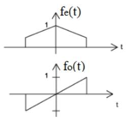
Note: Some functions are neither even nor odd. However, such functions can be written as a sum of even and odd functions. Any function f(x) can be expressed as a sum of an odd function and an even function.
Invertibility and Inverse Systems:
A system is said to be invertible if distinct inputs lead to distinct outputs. As illustrated in the figure for the continuous-time case, if a system is invertible, then an inverse system exists that, when cascaded with the original system, yields an output w(t) equal to the input x(n) to the first system.
An example of an invertible continuous-time system is y(t) = 2x(t),
for which the inverse system is w(t) = 1/2 y(t)
Causal System:
A system is causal if the output at any time depends only on values of the input at the present time and in the past. Such a system is often referred to as being nonanticipative, as the system output does not anticipate future values of the input. Consequently, if two inputs to a causal system are identical up to some point in time to or no the corresponding outputs must also be equal up to this same time.
y1(t) = 2x(t) + x(t-1) + [x(t)]2 ⇒ Causal Signal
y1(t) = 2x(t) + x(t-1) + [x(t+2)] ⇒ Non-Causal Signal
Homogeneity (Scaling):
A system is said to be homogeneous if, for any input signal X(t), i.e. scaling any input signal scales the output signal by the same factor.
Time-Shifting / Time Reversal / Time Scaling
Time Shifting is simply shifting the signal in time. When we add a constant to the time, we obtain the advanced signal, & when we decrease the time, we get the delayed signal.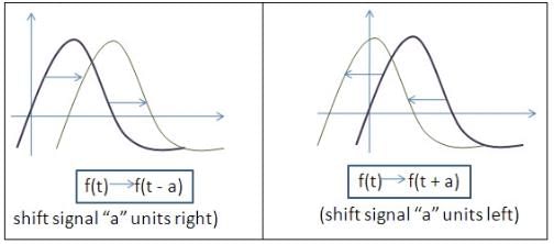
Time Scaling:
Due to the scaling in time the output Signal may shrink or strech it depends on the numerical value of scaling factor.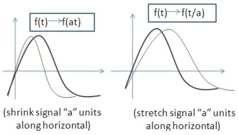
Time Inversion:
Time Inversion is simply flipping the signal about the y-axis.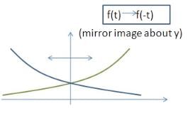
The Correlation Functions
Correlation is a mathematical operation that is very similar to convolution. Just as with convolution, correlation uses two signals to produce a third signal. This third signal is called the cross-correlation of the two input signals. If a signal is correlated with itself, the resulting signal is instead called the autocorrelation.
There are three basic definitions to define correlation function
(a) For an infinite duration waveform:
which may be considered as a “power” based definition.
(b) For a finite duration waveform: If the waveform exists only in the interval t1 ≤t ≤ t2.
which may be considered as an “energy” based definition.
(c) For a periodic waveform: If f(t) is periodic with period T.
for an arbitrary t0, which again may be considered as a “power” based definition.
Example: Find the auto-correlation function of the square pulse of amplitude a and duration T as shown below.
The wave form has a finite duration, and the auto-correlation function is
The auto-correlation function is developed graphically below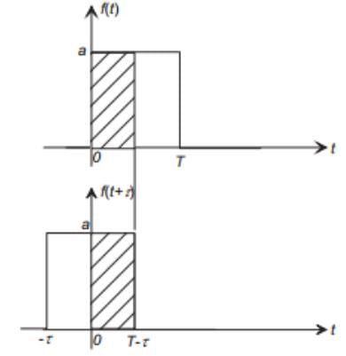
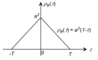


Properties of the Auto-correlation Function
- The auto-correlation functions φff (τ) and ρff (τ) are even functions, that is
φff (−τ) = φff (τ), and ρff (−τ) = ρff (τ) - A maximum value of ρff(τ) (or φff(τ) occurs at delay τ = 0,
|ρff(τ)| ≤ ρff (0), and |φff (τ)| ≤ φff (0)
and we note that is the “energy” of the waveform.

- ρff (τ) contains no phase information, and is independent of the time origin.
- If f(t) is periodic with period T, φff (τ) is also periodic with period T.
- If f(t) has zero mean (µ = 0), and f(t) is non-periodic, lim ρff (τ) = 0.
Note on the relative “widths” of the Auto-correlation and Power/Energy Spectra
- As in the case of Fourier analysis of waveforms, there is a general reciprocal relationship between the width of a signal's spectrum and the width of its auto-correlation function. A narrow autocorrelation function generally implies a “broad” spectrum
 and a “broad” autocorrelation function generally implies a narrow-band waveform.

In the limit, if φff (τ)= δ(τ), then Φff (j Ω)=1, and the spectrum is defined to be “white”.
The Cross-Correlation Function
The cross-correlation function is a measure of self-similarity between two waveforms f(t) and g(t). As in the case of the auto-correlation functions we need two definitions:
in the case of infinite duration waveforms, and for finite duration waveforms.
Example: Find the cross-correlation function between the following two functions.
In this case g(t) is a delayed version of f(t). The cross-correlation is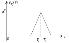
where the peak occurs at τ = T2 − T1 (the delay between the two signals).
Properties of the Cross-Correlation Function
- φfg(τ) = φgf (−τ), and the cross-correlation function is not necessarily an even function.
- If φfg(τ) = 0 for all τ, then f(t) and g(t) are said to be uncorrelated.
- If g(t) = a.f(t−T), where a is a constant, that is g(t) is a scaled and delayed version of f(t), then φff(τ) will have its maximum value at τ = T.
- Cross-correlation is often used in optimal estimation of delay, such as in echolocation (radar, sonar), and in GPS receivers.
The Cross-Power/Energy Spectrum
We define the cross-power/energy density spectra as the Fourier transforms of the cross-correlation functions: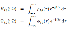


Rfg (jΩ) = (F−jΩ).G(jΩ)
Note that although Rff (jΩ) is real and even (because ρff(τ) is real and even,this is not the case with the cross-power/energy spectra,Φfg (jΩ) and Rfg(jΩ),and they are in general complex.
|
41 videos|52 docs|33 tests
|

|
Explore Courses for Electrical Engineering (EE) exam
|

|
 is the “energy” of the waveform.
 and a “broad” autocorrelation function generally implies a narrow-band waveform.


