Introduction to Single Phase Transformers | Electrical Machines - Electrical Engineering (EE) PDF Download
What are Transformers?

- The first electrical machine that we will pick up is transformers. Now as you will very soon see it is not really an electromechanical energy conversion device. It in fact, converts the voltage level of the AC supply.
- So, before we go into the constructional features or the operating principle of a transformer, I would like to show why a voltage transformation is required at all. Now the present electrical power generation plants work on the principle of economy of scale; that means the larger the power plant the cheaper will be the electricity generated by it, at least that is the belief; however, you can easily understand that such a large power plant cannot really be located near a dense populated city.
- There are many constraints, for example, space, environmental pollution, availability of raw material, water, and then coal. So, all these constraints usually determine where a power plant will be located, and it can be very long distance away from the point where the electricity will be ultimately used, and also all the electricity generated by a large power plant cannot be used at a single place.
- So, that brings in the question of transmitting large amount of electrical power that is in thousands of megawatts over very long distance more than hundreds of kilometers, and this has to be done efficiently in order to make the economy work.
How the Voltage level of transmission affects the efficiency of Power transmission?
- Let us say there is a load which needs P amount of power at a voltage of V and this power is being transmitted from a generating station which is some L meters away from the load.
 You can easily find out the current drawn by the load L:
 You can easily find out the current drawn by the load L:
 I = P/V
- Now the load is connected to the source using a transmission line; transmission lines are usually designed to operate at a constant current density J.
- Therefore, the cross-sectional area of the conductor,
a = I/J
- The resistance of the transmission line
R = ρL/a
where ρ is the resistivity of the transmission line material, L is the length, and a is the cross sectional area.
What is the total Power Loss in Transmission?
- Power loss
PL= I2R
- Transmitted Power is P, therefore I =P/V. Hence PL = (P/V)2 ρL/a
- So, PL/P ∝ to L/V.
- So, larger the voltage V smaller will be the power loss. So, that says that the power should be transmitted at the maximum possible voltage. So, how do we determine this voltage?Transformer used both at Generating end and at load end
- To transmit power from a generating station to the load, we need to build transmission towers. The higher the voltage, the taller the tower, and the more it costs to build. There is a point where the cost of building the towers outweighs the savings from reduced power loss. This determines the voltage used for transmission, which is typically a high value, like 400 kV or more.
- Generating electricity at such high voltages is not practical because it is difficult to provide insulation in the confined space of a generator. Therefore, power is usually generated at a lower voltage, around 11 kV. Similarly, at the load end, using high voltage is not convenient or safe, so the load also requires a lower voltage.
- To change the voltage levels at the generating and load ends, we use transformers. The general setup involves a generating station feeding a transformer, which connects to the transmission line. On the load end, another transformer connects to the load. Transformers themselves have some power loss, but they are designed to be highly efficient (often over 98%) to minimize this loss.
 Generating Station feeding Transformer
- The ability to easily change voltage levels at high efficiency is a key advantage of alternating current (AC) systems over direct current (DC) systems, making AC almost universally accepted for power transmission.
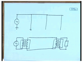
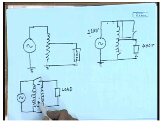
- Now let us see how this voltage transformation can be achieved? The simplest way to do it is to put a potential divider; that is you put a potential divider, and connect the load here. Well, it can work only for stepping down the voltage; of course, you can understand it is not possible to increase the load voltage above the supply voltage, not only that, there will be continuous power loss in the potential divider resistance. So, this is not very efficient. If it is an alternating circuit then this resistance can be replaced by an inductive potential divider. That will solve the problem of power loss, because an inductor in steady state will not consume any power, but then this circuit is not just an inductive potential divider; it is something more than that.
If you exchange the position of the load and the source; that is if you supply the power at this point and connect the load here, the load will see a voltage which is larger than the supply voltage. So, this construction as we will see is actually called an auto transformer, and we will have occasion to discuss it in more detail at later point of time. Here unlike a resistive potential divider the power transfer takes place both conductively through this path and also by magnetic induction because of flux coupling between the two sections of the windings. This is the principle of transformer, and since magnetic coupling does not require physical connection between the windings it is entirely possible to separate this auto transformer arrangement into two different windings.
For example, it will then look like this. These two windings are magnetically coupled, and power transfer takes place through this magnetic field. Now this arrangement has some advantage over this; just consider that there is a short circuit somehow between these two terminals. What will happen? If this side voltage is much larger than this; for example, this side if it is 11 KV and if this side is just 400 volts, as soon as there is a short circuit a single short circuit the load will see the full 11 kilovolt applied across it and will consequently be destroyed probably. The same fault here; the same fault here will not cause any such catastrophic failure.
In order to have this kind of a catastrophic failure here both end, at both end there should be a short circuit the possibility of which is far less. So, this construction is preferred over this construction of a transformer particularly in cases where the voltage levels on two sides are widely different. This is called the two winding transformer or simply the transformer. Now that we have mentioned the transformers work on the principle of magnetic coupling it will be worthwhile to recapitulate whatever we have studied regarding magnetic circuits, magnetic coupling, induced voltage in the basic electrical technology course once more.
 Now let us see how this voltage transformation can be achieved? The simplest way to do it is to put a potential divider; that is you put a potential divider, and connect the load here. Well, it can work only for stepping down the voltage; of course, you can understand it is not possible to increase the load voltage above the supply voltage, not only that, there will be continuous power loss in the potential divider resistance. So, this is not very efficient. If it is an alternating circuit then this resistance can be replaced by an inductive potential divider. That will solve the problem of power loss, because an inductor in steady state will not consume any power, but then this circuit is not just an inductive potential divider; it is something more than that.
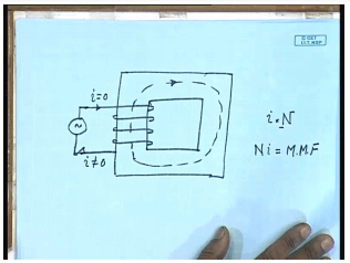
So, what is a magnetic circuit? By magnetic circuit we mean this kind of a construct. You have a core of some regular shape on which some winding is put. Now if there is no current flowing into this coil we do not expect any flux lines to be generated in this core; however, when you switch this source on and a current does flow then magnetic lines of force will circulate inside this core. The flux density or the magnet field intensity inside the core will depend on the magnitude of the current i into the number of turns in the coil N. This quantity multiplication of N and i is called the magneto motive force or MMF, and this magneto motive force causes a flux to circulate.
Magneto motive Force
So, we can see an analogy with an electrical circuit where the magneto motive force takes the place of MF or voltage source in an electrical circuit and the flux which is the effect takes the place of current which is the effect in a electrical circuit. From this analogy we call this a magnetic circuit; we will see further analogies later on. But before we get into how to draw this magnetic circuit let us recapitulate some fundamental laws regarding magnetic fields.
- We all know that if a conductor carries some current i, then at a point near the conductor, there will be a magnetic field.
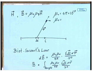
- A magnetic field can be characterized by a magnetic field intensity vector H or a magnetic flux density vector B.
- The relationship between these two is very simple. B is equal to mu naught mu R H, where mu naught is the permeability of free space and is given by 4 pi x 10-7.
- mu R is a dimensionless quantity. It is called the relative permeability of the material with which the core is made; for free space, mu R is one; for ferromagnetic material, it can be in thousands.
- Now the magnetic flux density, the incremental magnetic flux density at any point near a conducting wire due to a small length of the wire d L is given by the Biot-Savart's law, which says you can find out the incremental flux density d B; from the formula d B = mu naught mu R / (4 pi) * i dl cross r / r3, where r is the position vector of the point from the incremental length dl.
- Please note that the d B is a vector, and its direction will be determined by the cross product of i dl and r.
- In this case, r is in this direction, and i dl is in this direction; therefore, the direction of B will be out of this paper on the top.
- The total flux density B at that point due to the length of the wire can be obtained by integral equal to integral over length mu naught mu R / (4 pi) i dl cross r / r3.
- While this gives a general formula for determining the flux density near a conducting wire, in practice, this integration is difficult to perform except for a very simple structure of the current-carrying conductor.
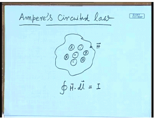
Therefore, for solving magnetic circuits we use a different formula which is the ampere’s circuital law. This says that the line integral of magnetic flux intensity H over a closed path is equal to the current total current enclosed. There may be several of them the total current enclosed; that is integral over a closed path H dot dl equal to the total current enclosed. This law is very convenient for finding out the flux density and the magnetic field intensity in magnetic circuits; let us see why.
- The structure of a magnetic circuit consists of a regular core and a winding.
- When the winding is excited, flux lines are inside the core.
- Almost all the flux lines are confined inside the core due to its high relative permeability compared to air or free space.
- The total amount of flux crossing the core at any position is fixed.
- The flux density along the flux line is constant, making the H constant over this path.
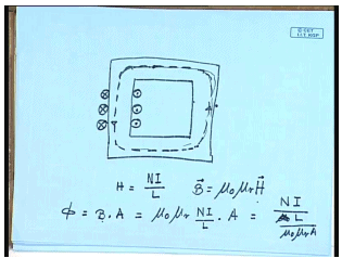
- In a closed path inside the core, H is constant, allowing the determination of H using the formula: H = NI / L.
- Finding the value of H and B (which is μ₀μᵣH) in a magnetic circuit is relatively simple.
- This method assumes that the leakage flux outside the core is almost negligible.
- The total flux (Φ) is related to the MMF (I) by Φ = B * A = μ₀μᵣNI / L * A.
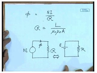
So, if N I is the MMF then flux phi can be written as phi equal to MMF N I by reluctance R where the reluctance R of the core is given by L divided by mu naught mu r A. So, if we extend the analogy that the MMF N I is equivalent to a source of potential, and flux is equivalent to a current in a magnetic circuit then the quantity reluctance is equivalent to resistance in an electrical circuit; therefore, a magnetic circuit can be represented by a MMF source N I which sends flux through a reluctance R.
The corresponding equivalent electrical circuit is a voltage source E sending a current through a resistance R; that is why this kind of a structure with a core with a winding on it is referred to as a magnetic circuit because of its similarity with an electrical circuit. In practice though this magnetic circuit is somewhat more complicated than a electrical circuit. In a electrical circuit the resistance is normally constant; however, in almost all practical magnetic circuits the core material is made up of ferromagnetic material.
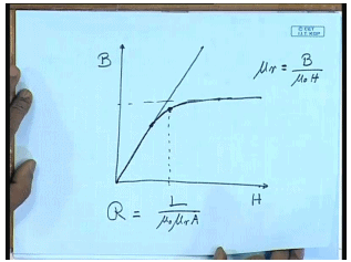
One property of this ferromagnetic material is that the relationship between the flux density and H magnetic field intensity is not linear; that is if we plot the flux density B versus the magnetic field density H. If it was linear then it would have been a straight line; however, for most material most practical ferromagnetic material it is not so. Initially it follows a straight line, but as v increases after some point this starts deviating from a straight line. In fact, B does not increase as fast as H, and beyond some point even if you keep on increasing H you practically do not increase.
This is due to the special constructional feature of this magnetic material which are made up of very tiny molecular level magnetic dipoles; however, almost all ferromagnetic material exhibits these characteristics which is called the B H characteristics, and that B H characteristics has a prominent saturation phenomenon where the relationship between B and H is nonlinear, and after a critical value of B further increasing H does not really increase B to a very great extent. Therefore, for ferromagnetic material the practical operating point that realizes the two potential of the material is somewhere in this junction in this region where the B H curves starts bending. This is called the knee point of operation.
Because given this point even if you put a large MMF that is H there will not be much increase in the magnetic flux density or the total magnetic flux circulated; obviously, in this region the relative permeability of the material which is mu R equal to B divided by mu naught H does not remain constant; therefore, reluctance of the magnetic core which is given by R equal to L divided by mu naught mu r A does not remain constant for all values of B. This is what makes analysis of magnetic circuit somewhat more difficult compared to analysis of an electrical circuit, let us see why.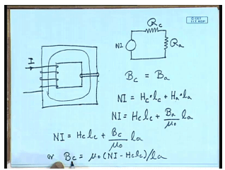
A magnetic core need not always be made of a single material. In many cases a magnetic core in addition to the ferromagnetic core material we will also possibly include an air gap. Now the relative permeability of the air gap and the magnetic core are very different. So, how we are going to find given a number of turns and the current flowing through it; how are we going to find out what is the total flux circulated? In this case where the magnetic circuit has two different types of material with two different relative permeability. In an electrical case it would have been simple. This is basically a series circuit; we could have drawn it for electrical case; we could have drawn it as a MMF source N I, reluctance of the magnetic path magnetic core R core in series with the reluctance of the air gap or air.
The problem with ferromagnetic material is that the value of R c is not known at priority, because it depends on the value of the flux density as we have already seen. The value of R a more or less remains constant, it is not a function of the flux density it is linear; the B H characteristics of air gap is linear. Therefore solving this involves is a little more involved, and let us see how we will solve this kind of a circuit. Although the field intensity may be different the total flux crossing the core material and the air gap of course same. If we neglect the fringing effect at the air gap then the flux density in the core and flux density in the air should also be same. The total MMF N I can be written as flux magnetic field intensity H c in the core multiplied by the length of the core plus field intensity in the air gap multiplied by the length of the air gap.
But the relationship between intensity in the air gap and the flux density is constant; therefore, N I equal to H c into L c plus H is equal to B air by mu naught since mu R for air gap is one into L a, but B a is equal to B c. Therefore, we can write N I equal to H c L c plus B c by mu naught L, a or B c equal to mu naught into N I minus H c L c by L a. This is one relationship relating B c to H c which is linear. The other relationship between B c and H c is given by the B H curve of the material.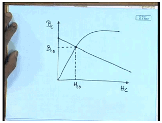
Now we plot them together H c on this axis and B c on y axis. This is the intrinsic B H characteristics of the material, and the other one given by the circuit which can be considered as a magnetic load line. The intersection of these two curves will give you the operating point H c 0 and B c 0. So, you see although solution of a magnetic circuit like this is somewhat more involved than solving an equivalent electrical circuit, but it can still be handled in a graphical manner, and this approach is used. At this point we think that we have discussed sufficiently about magnetic circuit. So, we will move to a different topic which is the induced voltage in a coil.
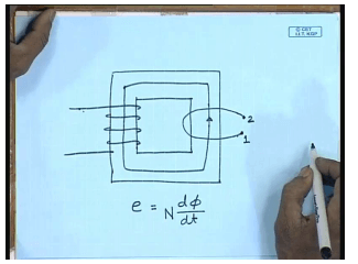
Let us say we have a magnetic core, and we are using a coil to set up magnetic flux in this direction. If the current flowing is into the coil is direct current then this flux will be a direct flux; however, if the core is excited with alternating current then the flux will also be alternating. We have seen the relationship between the flux and the current which is linear if the reluctance of the material can be assumed to be constant. The question now comes if I put another coil around this leg, what will happen? This has been studied by Michael Faraday, and the famous law says that there will be a voltage induced in this coil one, two. The magnitude of the induced voltage e will be proportional to the rate of change of flux density d phi d t multiplied by the number of turns in the coil N, and the polarity of the induced voltage will be such that it will try to oppose the very cause which it is due. Let us look at it a little more carefully what that means.
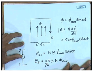
Let us say this is our coil, and there is a flux phi in the upward direction. This is a coil with let us say N turns, and there is a flux phi in this direction, and let the phi be varying in a sinusoidal fashion phi equal to phi max sin omega t. So, by Faraday’s law the induced voltage e will be such that magnitude e will be proportional to N d phi d t equal to N omega phi max cos omega t, and the direction of the polarity of the induced voltage will be such that it will tend to oppose the very cause which it is due; what is the cause that the changing of the flux. Now let us see at t equal to 0 the flux was 0, and as time progresses t becomes positive; this flux tries to increase.
So, in order to oppose that cause, what the induced voltage will try to do? If you close this switch this induced voltage e will send a current through this loop which will tend to cancel this current which will tend to cancel this flux; therefore, the circulating current will be generating a flux which will be in the opposite direction. So, what will be the direction of that current which we can cancel this flux; obviously, the current will be in this direction. Therefore, this coil with this kind of a flux can be replaced by an e. m. f source e where the terminal two at time 0 will be positive, and the terminal one at time 0 will be negative, and the potential e 21 in that case will be given by N omega phi max cos omega t. So, if we want to find out the r m s value then E 21 equal to omega is given by 2 pi f into N phi max divided by root 2.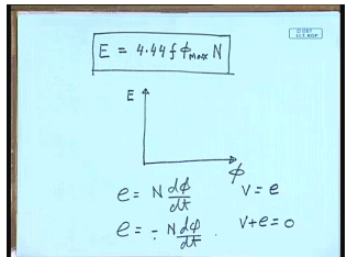
- Or the induced voltage E equal to 2 pi by root 2 is 4.44 f phi max N.
- So, this is the formula of induced r m s voltage in a coil with number of turns N which links an alternating flux I.
- Generally alternating quantities in ac circuit analysis are represented by phasors; therefore, if we draw the phasors and take the flux phasor to be the reference phasor then the induced voltage E will be leading it by an angle 90 degree.
- Here I would like to bring to your attention some of the conventions that are used by the authors of different books.
- The quantity that we have been calling induced voltage in fact by many authors is called the counter induced voltage, because here we have got this e by simply saying e equal to N d phi d t.
And we have incorporated the last part of the Faraday’s law that is it opposes the very cause which it is due by taking its proper polarity. This many authors call the counter induced voltage. The actual Faraday’s law says e equal to minus N d phi d t. So, in our case this e will be opposing the supply voltage in the case where e is taken with a negative sign. This is called the induced voltage; therefore, in our case the k v L of the coil will be written as v equal to e; in this case the k v L will be written as v plus e equal to 0 that is the only difference. In fact, if there is no scope of confusion then we will keep calling this as the induced voltage although many authors in some text books will be calling it the counter induced voltage.
|
19 videos|90 docs|25 tests
|
FAQs on Introduction to Single Phase Transformers - Electrical Machines - Electrical Engineering (EE)
| 1. What is a single-phase transformer? |  |
| 2. What is the difference between a step-up transformer and a step-down transformer? | |
| 3. What are the applications of single-phase transformers? | |
| 4. How do you calculate the turns ratio of a single-phase transformer? | |
| 5. What are the advantages of using a single-phase transformer? | |

|
8.7K Views |

|
4.94/5 Rating |

|
Dec 22, 2024 Last updated |

|
Explore Courses for Electrical Engineering (EE) exam
|
|
Extra Questions
,Previous Year Questions with Solutions
,Summary
,Important questions
,Exam
,practice quizzes
,Introduction to Single Phase Transformers | Electrical Machines - Electrical Engineering (EE)
,ppt
,shortcuts and tricks
,study material
,Introduction to Single Phase Transformers | Electrical Machines - Electrical Engineering (EE)
,Introduction to Single Phase Transformers | Electrical Machines - Electrical Engineering (EE)
,mock tests for examination
,past year papers
,Objective type Questions
,video lectures
,Free
,Sample Paper
,Viva Questions
,MCQs
,Semester Notes
;


Introduction to Single Phase Transformers Free PDF Download
Importance of Introduction to Single Phase Transformers
Introduction to Single Phase Transformers Notes
Introduction to Single Phase Transformers Electrical Engineering (EE) Questions
Study Introduction to Single Phase Transformers on the App
|
© EduRev
|
Education Revolution
|


|


