General EMF And Torque In DC Machines


General EMF and Torque in DC Machines
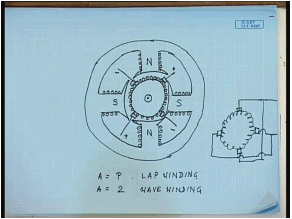
The study of a direct-current (DC) machine begins with its cross-sectional view and the arrangement of field poles, pole shoes, armature, commutator and brushes. A DC machine typically has stationary field poles mounted on the stator core. The poles are fitted with pole shoes which span most of the air-gap surface and carry the field winding. The field winding is excited by a DC current so that alternate north and south poles are produced. The rotating part of the machine is the armature (rotor) which is mounted on the shaft. Electrical connection to the rotating armature winding is provided by the commutator and brushes. The brushes normally sit near the inter-polar region and collect the voltage produced by the armature winding.
Physical arrangement, armature winding and parallel paths
The armature winding of a DC machine is a closed winding split into several parallel paths by the brushes. The brushes make contact with commutator segments such that the armature winding is divided into a number of parallel paths a. For a lap winding the number of parallel paths is equal to the number of poles P. For a wave winding the number of parallel paths is usually 2.
- Double-layer armature: DC machines commonly use a double-layer winding so each pole pitch contains two coil sides in different layers.
- Commutation and brushes: Brushes are usually placed near the inter-polar axis so that coil segments are switched by the commutator as the armature rotates. The commutator converts the alternating instantaneous coil voltages into a unidirectional terminal voltage (rectified waveform with many coils nearly smoothing the ripple).
Developed view of the armature and pole geometry
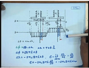
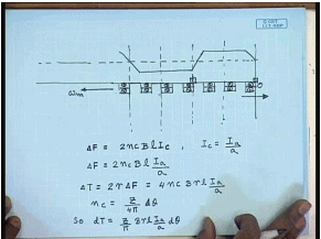
A convenient way to visualise the distribution of flux and coils is the developed (unfolded) view of the armature periphery. In this view the circular armature periphery is cut and laid out straight. Let the machine have P poles. The mechanical angular position of poles and inter-polar regions repeats every 2π/P radians. A flux density distribution on the air gap due to field winding may be approximated as a flat-top (trapezoidal) waveform under the pole shoes and near zero in the inter-polar regions. Positive flux flows from north pole into the armature; negative flux flows from the armature to the south pole.
Induced EMF in an armature coil - derivation from first principles
Consider a full-pitch armature coil whose one end lies under the north pole and the other under an opposite south pole. Let the armature rotate with angular speed ωm in the direction shown. Let the instantaneous angular position of the coil be θ at time t and θ + Δθ at time t + Δt where Δθ = ωm Δt. The change of flux linkages of the coil gives the induced EMF (Faraday's law).
Derivation (step-wise):
Flux change corresponding to a small angular motion Δθ is the flux leaving the coil from the positive pole region and the additional negative flux entering - combined change is
ΔΦ = -2 B r l Δθ
where B is the local air-gap flux density under the pole, r is the armature radius and l is the axial length of the armature.
Flux linkage change for the coil (with nc turns per coil) is
Δλ = nc ΔΦ = -2 nc B r l Δθ
The instantaneous induced EMF in the coil is
e = -dλ/dt = 2 nc B r l (dθ/dt)
Since dθ/dt = ωm,
e = 2 nc B r l ωm
This shows that the instantaneous coil EMF is proportional to the local flux density at the coil position and to the rotational speed.
EMF waveform, commutator action and terminal voltage
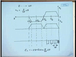
The instantaneous induced EMF in a single coil follows the same spatial waveform as the air-gap flux density. However the voltage seen at the brushes is not the same as any single coil EMF because coils are connected through the commutator and many coils share the load in parallel/series according to the winding connection. A single coil would produce an alternating waveform; the commutator reverses connections so the brush voltage becomes a rectified waveform. With many coils distributed on the periphery, the summation of contributions from many coils produces a nearly DC terminal voltage (with small ripple).
From coil EMF to generated (or back) EMF: flux per pole and conductor count
Let Z be the total number of armature conductors distributed uniformly over the armature periphery. In a double-layer winding the conductors are arranged so that a coil occupies a small mechanical span Δθ. The number of turns in a coil nc may be related to conductor distribution. Rather than details of coil geometry, the induced terminal voltage between brushes can be obtained conveniently by integrating the coil EMF contributions over the pole pitch and accounting for the number of coils in series between the brushes.
Define Φp as the flux per pole (that is, the total flux under one pole). Then the induced voltage between brushes (the generated EMF or back EMF Eb) for a machine rotating at angular velocity ωm is obtained as follows.
Derivation (step-wise):
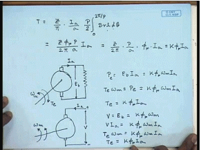
Average coil EMF per unit angular span relates to B r l and ωm and integrating over the pole pitch gives the flux per pole Φp = ∫ B r l dθ over the pole.
Number of series conductors contributing between the brushes leads to the factor Z/A where A is the number of parallel paths in the armature.
Multiply by the number of poles P to account for all poles around the periphery and use the relation between angular frequency and time to get the terminal EMF.
Putting the constants together yields the standard expression
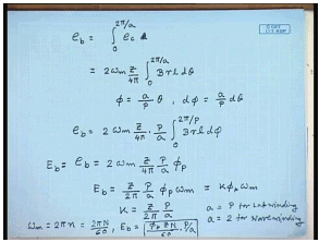
Eb = (Z P Φp ωm) / (2π A)
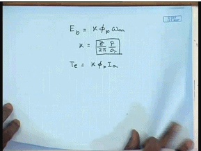
Define the constant k = (Z P) / (2π A). Then
Eb = k Φp ωm
Expressed in terms of speed in revolutions per minute (N in rpm) using ωm = 2π N / 60, the commonly used form is
Eb = (P Φp Z N) / (60 A)
All variables are as defined:
- Z: total number of armature conductors.
- P: number of poles.
- Φp: flux per pole (weber).
- A: number of parallel paths (A = P for lap winding; A ≈ 2 for wave winding).
- N: speed in rpm.
- ωm: angular speed (rad·s-1).
- k: machine constant (back-EMF constant).
Torque production - direction and magnitude
When armature conductors carry current in the presence of the field flux, each conductor experiences a force given by Fleming's left-hand rule. The force on a conductor of active length l carrying current Ic and placed in flux density B is F = B l Ic per conductor (for one conductor). In the double-layer coil, consider the two conductor sides under opposite poles; forces produce a couple (torque) about the shaft.
Derivation of torque (step-wise):
Force on conductors belonging to a coil set at a given angular position is ΔF = number of conductors at that position × B l Ic.
With double layer and nc turns per coil the number of active conductors contributing in a small region is 2 nc, hence
ΔF = 2 nc B l Ic
Armature current shared among parallel paths gives Ic = Ia / A where Ia is the total armature current.
Hence ΔF = 2 nc B l (Ia / A)
The torque contribution from that conductor group at radius r is ΔT = r × ΔF (or two sets of conductors diametrically opposite give an extra factor 2), resulting in
ΔT = 4 nc B r l (Ia / A)
Express nc in terms of conductor distribution and integrate over one pole pitch; multiply by number of pole pairs (P/2) to account for all poles. Identifying the integral of B r l dθ as flux per pole Φp leads to the total electromagnetic torque
T = (Z P Φp Ia) / (2π A)
Using the machine constant k defined earlier,
T = k Φp Ia
Power balance and relationship between torque and back EMF
For an ideal machine (neglecting losses) the electrical power converted by the armature equals the mechanical power at the shaft. When the machine acts as a generator the electrical power developed is Eb Ia and the mechanical power developed (output) is T ωm. Equating these gives
T ωm = Eb Ia
Substitute Eb = k Φp ωm to get
T = k Φp Ia
This confirms that the torque constant equals the back-EMF constant and that torque is proportional to flux per pole and armature current. The same expression holds in motoring mode; only the direction (sign) of torque and current changes.
Motoring and generating modes - sign convention and physical meaning
- Generating mode: The armature is driven at speed ωm and an EMF Eb = k Φp ωm is induced. If the armature circuit is closed through a load, current flows and the electromagnetic torque produced opposes the driving torque (i.e., it opposes rotation). Mechanical work is converted to electrical output.
- Motoring mode: An external supply forces armature current Ia into the armature; the electromagnetic torque produced assists rotation (same direction as rotation) and electrical power is converted into mechanical output.
- In both modes the magnitudes follow the same relations Eb = k Φp ωm and T = k Φp Ia. Only the signs (directions) differ according to the mode of operation.
Winding types and the constant k
The constant k depends only on the winding and conductor geometry and the number of poles. For practical windings:
- Lap winding: A = P, therefore the parallel paths equal the number of poles.
- Wave winding: A ≈ 2 regardless of P (for typical wave windings).
- Using these values of A changes the numerical value of k = (Z P) / (2π A) for otherwise identical machines.
Practical notes and smoothing of terminal voltage
Although individual coils produce alternating-polarity EMFs as they rotate, the commutator and the large number of distributed coils combine to produce a nearly steady DC terminal voltage. Ripple is reduced by:
- Using many coils and slots (large Z).
- Choosing appropriate coil pitches and distribution factors.
- Using interpoles and compensating windings to improve commutation and reduce sparking.
Worked numerical example
Example: A DC machine has Z = 720 armature conductors, P = 4 poles, A = 4 (lap winding), flux per pole Φp = 8 × 10⁻³ Wb, and rotates at N = 1200 rpm. Find the generated EMF Eb and the torque constant k. If the armature current Ia = 50 A, find the electromagnetic torque.
Solution (step-wise):
ωm = 2π N / 60
ωm = 2π × 1200 / 60 = 40π rad·s-1
k = (Z P) / (2π A)
k = (720 × 4) / (2π × 4) = 720 / (2π) = 360 / π
Eb = k Φp ωm
Eb = (360 / π) × 8×10-3 × 40π
Eb = 360 × 8×10-3 × 40 = 360 × 0.008 × 40
Eb = 115.2 V
Torque T = k Φp Ia
T = (360 / π) × 8×10-3 × 50
T ≈ (360 × 0.008 × 50) / π = (144) / π ≈ 45.8 N·m
Summary
The induced EMF and electromagnetic torque in a DC machine follow simple, fundamental relations when flux per pole and armature parameters are accounted for. The standard formulae are
Eb = k Φp ωm = (Z P Φp ωm) / (2π A)
T = k Φp Ia = (Z P Φp Ia) / (2π A)
Here Φp is flux per pole, Z is total armature conductors, P is number of poles, A is number of parallel paths, ωm is angular speed and Ia is armature current. The same constant k appears in both expressions, which reflects energy conversion balance: electrical power Eb Ia equals mechanical power T ωm in the ideal lossless case.
FAQs on General EMF And Torque In DC Machines
| 1. What is EMF in a DC machine? |  |
| 2. How is torque generated in a DC machine? | |
| 3. What factors affect the magnitude of EMF in a DC machine? | |
| 4. How does the armature winding affect torque in a DC machine? | |
| 5. How can the torque in a DC machine be increased? | |


 | Explore Courses for Electrical Engineering (EE) exam |
 | Get EduRev Notes directly in your Google search |