Characteristics of DC Shunt Motors
(Refer Slide Time: 00:24)

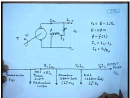
In the last few classes, we have seen that a DC machine can work as a generator when its armature is rotated with a prime mover, and when excitation is provided to the field winding which produces the flux. However, when we have seen that we can connect a load, so that current will flow into it. However, it is not essential that a load is connected. Just a resistance is connected. It can as well be connected to a constant DC supply of voltage V t. Even then it will work as a generator provided the prime mover can run the armature at a speed, such that the generated voltage E is larger than the terminal voltage V t.
So, the armature current will flow in this direction. Since, the terminal of the generator I have already connected to a constant voltage source, we can as well connect the field winding across the armature. Now, it will not behave really as a shunt generator, but it will behave like a separately excited generator with a constant voltage applied across the field in order to vary field flux. It is possible to provide a resistance which can be controlled to control the field current. Now, for this generator, we can write V t equal to E minus I a R a, where E equal to k phi. Omega phi is given by the saturation characteristics as function of I f and I L equal to I a minus I f, where I f equal to V t by R f.
If we look at the power distribution, then you find that let the rotational speed of the shaft be omega and the talk provided by the prime mover be t, then the power input power output by the prime mover is p, mechanical p prime mover equal to t omega. Now, the part of the power provided by the prime mover will be lost into mechanical loss that is frictional vintage losses. So, this is a part goes out as mechanical losses. So, this is the mechanical power provided to the net mechanical power input to the generator. This is equal to also E I a.
Next power loss component is the armature copper loss I a square R a. Next loss is the field copper loss which is I f square R f. Finally, the rest is the output power which is V t I l. So, the current here is, this is voltage induced is E a I a. Here, the voltage is V t I a, and here the voltage and current is V t I l. So, this is how the power flow picture will look like in this is operating as a generator. Obviously, in order for this system to work as a generator, the prime mover should be rotated. It should rotate the armature at a speed, such that with the given field excitation, the generated E m f across the armature is larger than the supplied terminal voltage and then only, it will work as a generator. Now, what will happen if the rotational speed is less such that E is less than V t? In that case, the direction of current through the same generator will reverse and now, the machine will work as a motor.
(Refer Slide Time: 07:21)
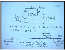
We see that in a generator mode of operation, the power input is the mechanical power input from the shaft and the output power is the electrical power which may be consumed by a resistive load, or can be fed back to the supply. So, it is not essential in order to operate this machine as a generator to have a DC supply available. This can work very easily as a self excited shunt generator supplying an insulated resistive load, but the situation is different for a motor mode of operation. Here, also the armature is connected to a DC supply of terminal voltage V t a field winding connected across the same supply.
Hence, you can call it a shunt gen motor or a separately excited motor because they are connected at the same supply voltage. Normally, an additional resistance R f will be connected in the field in order to control the field current. This will produce a flux of phi f. Now, let us say at any prime, it is rotating at a speed of omega. In that case, the induced voltage E equal to k phi omega as in the previous case and we are assuming that this is less than V t. So, for this case, the current will flow into the armature and we can write V t equal to E plus I a R a I a equal to I L minus I f I f equal to V t by R f, and phi f is a non-linear function of I f given by the magnetization characteristics a power flow in this case. Now, here the input power is electrical power. That is why it is essential that a DC source be present for motor mode of operation.
So, p input, this is electrical. This is equal to V t I L. The first loss encountered is the field copper loss. So, the current here is I a, and here the current was I L. Next is armature copper loss.
So, this is the developed power E a I a which is converted to mechanical power. Next is the mechanical losses and the mechanical power output. So, in order to get some mechanical power output, it must be connected to a load which will provide a opposing torque t L and in steady state t L omega equal to E I a. So, you see that the same machine connected to the same supply can work either as a motor or as a generator that depends on what is the value of the back E m f at the given operating speed. If it is larger than the terminal voltage, then the machine will operate as a generator. Otherwise, it will run as a motor.
(Refer Slide Time: 14:00)
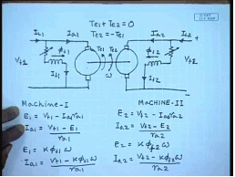
Therefore, suppose now I connect two such machines back to back, mechanically couple them and supply from 2 DC sources. Let us say this is V t 1, this is V t 2 and this is I L 1, this is I L 2, this is V t 1, V t 2, I a 1, I a 2, I f 1, I f 2, this flux is phi f 1, this is phi f 2. Let the whole set be rotating at a speed of omega and let us say, this is the generated talk. Te 1 of this machine and this is the generated talk Te 2 of this machine. Now, how to determine which machine will be motor and which machine will be generator?
Now, for that we need to find out the talk speed characteristics of the machine. Let us say for machine 1, we know E 1 equal to V t 1 minus I a R a 1 or I a 1 equal to V t 1 minus E 1 by R a 1, but E 1 equal to k phi f 1 omega, so I a 1 equal to V t 1 minus k phi f I 1 omega by R a 1. Similarly, for machine 2, E 2 equal to V t 2 minus I a 2 R a 2 I a 2 equal to V t 2 minus E 2 by R a 2 E 2 equal to k phi 2 phi f 2 omega and I a 2 equal to V t 2 minus k phi f 2 omega by R a 2.
(Refer Slide Time: 18:22)
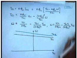
Now, what are the talks? Te 1 and Te 2. Te 1 equals k phi f 1 I a 1. This is equal to k phi f 1 and I a 1 is given by V t 1 minus k phi f 1 omega by R a 1. This can also be written as Te 1 equal to k phi f 1 by R a 1 V t 1 minus k phi f 1 whole square by R a 1 omega or in other words, we can write omega as k phi f 1 minus. So, this is the equation of straight line and if we plot it, this is omega Te 1 at Te 1 equal to 0. This is the no load operation. It looks like a straight line like this. Similarly, for the second machine, we can write omega equal to V t 2 by k phi f 2 minus R a 2 divided by k phi f 2 whole square Te 2, and if I plot that may be looking somewhat like this. This is Te 1, this is Te 2.
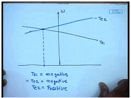
Now, let us go back to the original arrangement. You see that the two motors are mechanically coupled. So, in steady state, there should be no made set of, that is it is necessary that Te 1 plus Te 2 equal to 0, that is the machine will operate at such a speed such that Te 1 plus Te 2 equal to 0 or in other words, Te 2 should be equal to minus Te 1 or Te 1 equal to minus Te 2, so instead of plotting Te 2, if we plot minus Te 2. So, this is Te 1 and then I plot minus Te 2. It will be something like this. We find that this is minus Te 2.
(Refer Slide Time: 23:50)
We find that the operating point is, actually in this case, we will have Te 1 will be negative and minus Te 2 is negative. That means Te 2 is positive. What does positive and negative mean? In this sense from the diagram we see that any talk that assist the mechanical motion, that is in the direction of motion is assumed to be positive and any talk that is in direction opposite to the motion, that is which tries to slow down the motion is negative.
So, from the mechanical power point input point of view, any talk, the generated talk, if it is assisting the mechanical motion, then mechanical power is input to the machine. That means that machine is operating as a motor. The developed mechanical power assists motion. That means, electrical power is getting converted to mechanical power and causing motion. So, that is a motor and if the developed electrical torque opposes motion, then the mechanical power that is the machine is driven against the opposing torque. Then the mechanical power is input to that machine and that machine operates as a generator. Hence, we find that in this case Te 1 is negative. That means, the talk generated by machine 1 is opposing motion. Hence, it is operating as a generator while talk generated by machine 2 is positive. It is assisting motion. This is operating as a motor.
So, we find that if the torque speed characteristics of a machine is above the other, then that works as a motor naturally, because then it will try to drive the other machine at a higher speed and hence, the other machines backing if will be larger than terminal voltage and it will operate as a generator, we could have reversed the roles particularly if we find that the torque speed characteristics depends on several parameters.
(Refer Slide Time: 27:56)
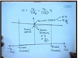
The expression for the torque speed characteristic is speed equal to V t by k phi minus R a by k phi square to Te, and without assume positive direction of current flowing into the machine, the motoring mode torque is positive and the generating mode torque is negative. Since, in a DC machine with constant field flux, torque is proportional to armature current. So, this x axis also to scale represents the armature current. This is the speed at which torque is 0 indicating the machine is operating at no load if we neglect mechanical losses. So, this is the no load speed. We see that this no load speed with t equal to 0, this is proportional to the terminal voltage and inversely proportional to the field flux. This is slope and let us say, this is the rated armature current and hence, the corresponding T e rated. Hence, corresponding to I a rated in the generating side, also there will be a minus Te rated by…
So, although we see that if this is the no load speed, this will be the rated speed which is somewhat lower than the no load speed. Hence, there is a load, there is a speed drop at load which is proportional for, speed drop is proportional to R a proportional to Te and inversely proportional to phi f square. So, if we change these parameters, how do you think the characteristics is going to change?
(Refer Slide Time: 32:15)
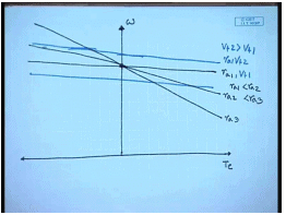
So, let us say at any terminal voltage, this is the torque speed characteristics. Simplest thing keeping everything else same. If additional resistance is included in the armature winding, then this is R a 1, this is R a 2. R a 1 is less than R a 2. So, the slope of the torque speed characteristics can be changed. Similarly, keeping the armature resistance constant R a 1, if we increase the armature voltage in the torque speed characteristics sits parallel upward, its slope remains same. This is R a 1 V t 1, this is R a 1 V t 2 and V t 2 is larger than V t 1, but if we reduce, then torque speed characteristics also moves down.
(Refer Slide Time: 34:34)
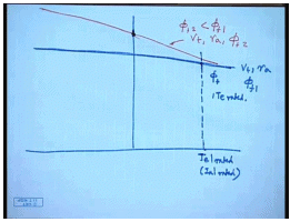
What happens? If we change the field flux by changing the field resistance? This was say for terminal voltage V t resistance R a, and field flux phi f 1. Suppose, I reduce the field flux to a value phi f 2, then naturally the no load speed will increase, but the slope will also increase. This is V t R a phi f 2 with phi f 2 less than phi f 1. It will be interesting to find out how far we can reduce this field flux. In fact, we cannot increase the field flux very much because of saturation. The machines are almost always works at rated flux. We can reduce it, but cannot increase it very much. So, we will consider only decrease of field flux and not increase. It will be interesting to find out how far we can reduce this field flux.
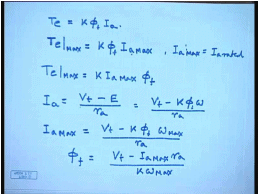
Now, we have seen that we cannot operate the machine anywhere on these characteristics because of limitation of the armature current. So, only that much torque can be generated which corresponds to rated armature current. So, with rated flux phi f, this is the Te rated that we can generate if I reduce the flux.
(Refer Slide Time: 37:21)
Let us say to phi f 1, what will happen? The armature current will still remain same. So, the torque generated Te is k phi f I a. The maximum torque that can be generated irrespective of the value of phi is at any given flux. So, at any reduced flux, the maximum power that can be generated since I a max is constant which is equal to I a rated. Then Te max is equal to k I a max phi f. What is the corresponding machine speed at a current of I a max? We know I a equal to V t minus E by R a equal to V t minus k phi omega by R a. So, I a max equal to V t which is constant minus k phi f corresponding omega max by R a. So, what is phi f? If for a constant value of I a, what is the relationship between I a, and phi a, and omega phi f equal to V t minus I a max R a by k omega max.
(Refer Slide Time: 40:23)
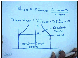
So, substituting this, we get Te max. We find that everything on the right hand side is constant. That means, Te max omega max equal to constant. So, when you reduce field flux, it turns out that within the given armature current limit, the maximum mechanical power that you can develop either in the motoring or in the generating mode is constant. So, the operating point the machine must be operated bounded by these two vertical lines which indicate the armature current limit, and this rectangular hyperbola which are indicated, which are restricted again by armature current limit, but when the field flux is reduced below its rated value. So, this is called the maximum power, the constant power operating zone, constant power zone.
Now, below this corresponds to rated armature voltage. We are by some means if we can reduce the armature voltage below the rated value, then the limits corresponding to rated armature current become straight line. So, this and you can generate constant maximum rated torque. This is called the constant torque zone. A DC shunt machine must. The operating point of the DC shunt machine must be within this region, so that the armature current limit is not exceeded whatever way we may achieve that.
(Refer Slide Time: 44:10)
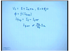
Now, so far we have neglected armature reaction. We have written V t equal to E minus I a R a and E plus I a R a and E equal to k phi f omega, where phi f equal to function of I f, but when you consider armature reaction, this should be phi f equivalent. Now, I f equivalent equal to I f minus I f corresponding to armature reaction. Now, I f armature reaction in means most cases is proportional to armature current. Therefore, physically what happens is that as the motor is loaded, the armature current increases. As the armature current increases, armature reaction becomes more prominent and hence, the effective field flux reduces and hence, the generated voltage reduces. So, more current flows and the torque increases.
(Refer Slide Time: 45:56)
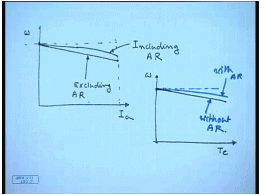
Therefore, if the effect on the torque speed or current speed characteristics is somewhat like this, suppose if I draw the current I a verses speed at no load current is 0. If we neglect armature resistance, then armature reaction, then as the speed decreases, the current increases linearly, but if we include armature reaction, then what happens is that for a given current, the speed does not drop as much it is above this and somewhat nonlinear. This is excluding armature reaction, this is including armature reaction.
Since, torque is proportional to armature; the torque speed characteristics will also look similar. This is the no load torque 0. Ideally, if no armature reaction was there, it would have dropped linearly, but when one takes into account the effect of armature reaction, the actual torque speed characteristics lies somewhat above this. So, this is with armature reaction, this is without armature reaction. We will see how it effects quantitatively through few examples.
(Refer Slide Time: 48:55)
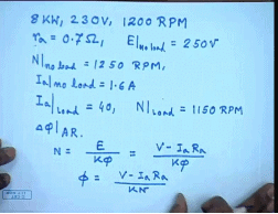
Let us say, we have a DC machine 8 kilowatts, 230 volts, 1200 RPM. The armature resistance r a equal to 0.7 ohm and no load voltage, the field current is tested the no load voltage set at E at no load and set at 250 volts. The motor runs at no load is 1250 RPM and draws armature current 1.6 amperes. Now, under this condition, you apply a load such that under loaded condition, I a, becomes equal to 40 ampere and N at load becomes equal to 1150 RPM. Find out how much reduction in flux per pole happens? Delta phi f due to armature reaction.
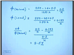
Now, we know the speed N equal to E divided by k phi equal to V minus I a R a by k phi or phi equal to I a R a by k n. So, phi at no load was, at no load V was equal to 250 volts, Ia was 1.6 amperes into R a was 0.7 and the speed was 1250 RPM.
(Refer Slide Time: 52:15)
So, this was equal to 0.2 by k and phi on load becomes 250 minus 40 into 0.7 by 1150 k. So, this is equal to 0.193 by k. So, delta phi by phi no load, this is equal to 0.2 by k minus 0.193 by k divided by 0.2 by k. This comes to 3.5 percent. So, from actual measured data, we can find out the effect of armature reaction on the field flux.
Thank you.