Starting of DC Shunt Motors
Let us solve one more problem regarding the characteristics of DC shunt motor before we move on to the next topic.
(Refer Slide Time: 00:32)
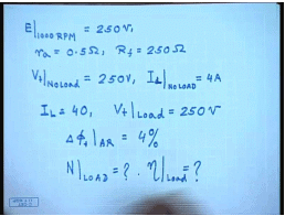
For this let us assume a DC machine when operated as a generator at 1000 RPM, E is the shunt machine gives a terminal voltage of 250 volts. Machine has a armature resistance of 0.5 ohm and a field resistance R f equal to 250 ohm. Now at no load when from as a motor operated as a motor and supplied from a source of same 250 volt, the armature current drawn equal to 4 amperes. The current drawn from the supply is 4 amperes. Now I load this motor up to a I L equal to 40 ampere supplying from same V t at load equal to 250 volt.
Suppose it has been found that delta phi f due to armature reaction equal to 4 percent just as we found out in the previous problem. Now we are excepted to find out the speed at the above load and the efficiency of the generator at load. How do we proceed about this? First let us try to find out the generated voltage at 1000 RPM when run as a generator.
(Refer Slide Time: 03:13)
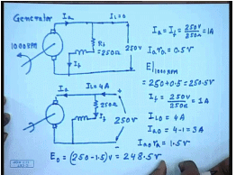
So, this machine was run as a generator at 1000 RPM as a shunt generator. This is R f equal to 250 ohm, and when run at a 1000 RPM the generated voltage was 250 volts. This being a shunt generator in the generating mode this current I a equal to I f and I L equal to 0. So, under this condition since the generated voltage is 250 volt, then I a equal to I f equal to 250 volts by 250 ohm; this is equal to 1 ampere. So, under this condition I a r a equal to 0.5 volts since r a equal to 0.5 ohm. So, the generated voltage E at 1000 RPM equal to 250 plus 0.5 equal to 250.5 volts.
Now let us try to find out the no load speed when this machine is run as a motor. This is the generator. This again is supplied from a 250 volt supply, the same field winding of 250 ohm resistance; the load current drawn is 4 ampere. So, let us try to find out what is the no load speed. So, I f is again 250 by volts by 250 ohm that is 1 ampere. I L at no load equal to 4 ampere. So, I a 0 equal to 4 minus 1 equal to 3 amperes. I a 0 r a equal to 1.5 volts. So, E 0 equal to 250 minus 1.5 of volt equal to 248.5 volts .
(Refer Slide Time: 07:11)
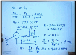
So, what will be no load speed? N 0 is proportional to E 0 because field current is same. So, N 0 by 1000 RPM equal to E 0 by that Emf at 1000 RPM; that is 250.5 equal to 248.5 minus 250.5 which is equal to. So, N 0 from here we kept as 992 RPM. So, at load condition and again supplying from a 250 volts source, the load current drawn I L equal to 40 ampere; this is still 250 ohm. So, this is I f equal to 1 ampere and I a equal to 39 amperes.
So, what is E under load condition? 250 minus 0.5 into 39. This gives you 230.5 volts. Now E by E 0, E is proportional to K phi N. So, E by E 0 equal to phi at no load N 0 by phi at load condition phi N. Now it is mentioned phi equal to 0.96 phi 0 due to armature reaction. So, N equal to E by E 0 into phi 0 by phi into N 0. This comes to 958.5 RPM. Interesting to see that if phi 0 and phi would have been same,, then speed drop would have been more, because this quantity is larger than 1. phi 0 by phi is equal to 1 by 0.96.
(Refer Slide Time: 12:36)
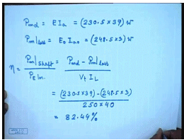
So, how do I find out the efficiency under load condition? The developed mechanical power under load condition P m developed equal to E into I a. This is equal to 230.5 into 39 so many watts. What is the mechanical loss? Now at no load we see that the armature current is not 0; it is 3 amperes. What happen, but there is no load connected to the shaft; that is the actually the mechanical loss. So, P m loss equal to E 0 I a 0. This is equal to 248.5 into 3 watts.
So, the shaft power output by efficiency equal to shaft power output divided by P electrical input. This is equal to V t I L. This comes as 230.5 into 39 minus 248.5 into 3 divided by 250 into 40. This comes to 82.44 percent. So, we see that if the data is known we can find out different performance parameters like speed, efficiency, current, etcetera, for a shunt DC motor. But before a DC motor can be used to supply a load, it must be started; how do I start a DC motor?
(Refer Slide Time: 15:14)
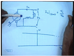
The simplest approach will be to connect both the armature and the field to the available supply voltage V t, then the sub course can be done theoretically, but this approach has some problem. Let us look at what the situation is. The torque speed characteristics of this DC motor looks like this. This is omega. This is T E and to some scale also I a. Now at start omega is equal to 0. So, what will be the torque? That will be obtained by extending both these lines. So, we can very easily see that at start there will be a huge current and a correspondingly huge. This is obvious, because at start the back Emf is zero. So, the armature current I a at start equal to V t by R a.
Now this R a is a very small value, because if we want high efficiency at loaded condition we cannot have a very large armature resistance. For very large machines this I a may be as small as 1 per unit 1 percent; at for even small machine it will not be more than 10 percent. So, you can except anywhere from 10 to 100 times the rated motor current to flow if a is connected directly across the supply voltage. So, how to overcome this problem? If the armature voltage can be made variable then of course, we can start with a very low voltage and overcome this problem; however, more often than not only a fixed voltage source will be available.
(Refer Slide Time: 18:17)
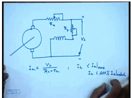
So, the next simplest approach is to connect a armature resistance in this manner. There are two resistances one connected in the armature circuit. So, with this during start we can write I a equal to V t divided by capital R a plus intrinsic armature resistance R a. So, by choosing appropriate value of R a, we can restrict I a less than the I a max. Generally it is I a max will not be less than 200 percent of rated I a; much larger I a is usually not acceptable particularly for a DC machine, because as we know that a DC machine contains a commutator and brush arrangement. So, where there is continuous making and breaking of the circuit.
So, if a very large current flows there will be added sparking at the commutator which may damage the commutator segments; otherwise, even a very large starting current will also cause a very large starting torque, which may be detrimental to the mechanical system of the motor or its coupling to the load. Also most supply system will not permit very large current to be drawn as it will be found if the motor is operated directly from the supply during start. So, we add a additional resistance to limit the current, but then what happens?
(Refer Slide Time: 21:04)
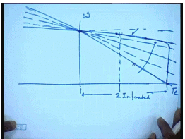
Once we add the resistance the motor characteristic changes. This was the intrinsic characteristics and possibly this is the characteristics with the added resistances. This is possibly two times I a rated, but then we see that although at start the motor draws two times rated current. As the speed of the motor increases the operating point moves along this line. So, as the motor speeds up the currents starts reducing; that way the acceleration of the motor becomes slow. So, for the whole duration of starting the armature current does not remain fixed. So, one approach is to use a variable armature resistance.
So, if one use a rheostat the armature circuit and adjust the rheostat so that as the motor speeds up, the resistance is also changed. So, that as the motor speeds up you keep changing the resistance. So, that the current remains more or less constant at its initial value up to the point where it has almost reached steady state, but then I allow for the resistance so that the motor comes to the normal operating point. This will be the ideal characteristics. However, in practice it is difficult to vary the armature resistance continuously and therefore, sectionalized step resistance starter are normally used for DC motor starting.
Another point that should be kept in mind is that before the armature resistance, the motor supply is given to the armature circuit. The field circuit must be excited first, because field has a large inductance in addition to the resistance of L f and the current in the field will take some time to develop. And until and unless field current has reached its full value the field flux will not reach its full value, and the back Emf which is given by omega will not reach its full value at a given starting speed at. So, it is necessary during starting to have the flux at its rated level at the maximum level, so that as soon as there is some speed developed some back Emf is developed and the current flowing through the machine is restricted.
So, during starting the field resistance must be completely shorted to allow maximum current to flow through the field circuit even before the voltage is applied to the armature. After the field current has been established, the voltage can be applied to the armature with the armature resistance at its maximum position, so that the casting current through the machine is limited. And then preferably the armature current should be cutout as the speed of the machine increases, so that the machine accelerates at within a reasonable time. However as we mentioned that it is difficult to get a continuously variable armature resistance; therefore, step resistance starters are normally used for DC shunt motor starting. We will explain the working principle of one of them.
(Refer Slide Time: 25:54)
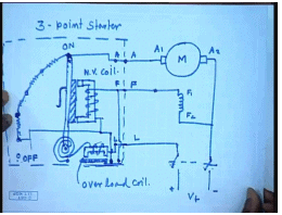
Let us say this is the DC motor to be started. So, this is one of the armature terminals. This is the plus minus supply V t. This is called the load terminal; these are the three terminals to which a starter is connected. So, what are the things in the starter? The starter consist of several sections of resistance and a conducting and a handle to connect them. This handle is spring loaded. This load line is connected to this spring and to this handle through a electromagnet. One of this armature terminal is connected to the last point. This handle is variable, this movable with a external insulated shaft.
So, these are three corresponding terminal on the starter. On the handle there is a soft iron piece. The field winding is connected in series with the coil of another. This is the starter arrangement. Since, there are three connecting points on the starter as in the armature, this is called the 3-point starter . So, initially this handle is in off position. When we switch this on switch on the supply, then first field circuit is excited through this, through this, and through this line. When we put this on first and move this handle to this off position, the field circuit first gets excited and then armature also gets it supply; this is in this position.
So, through this line armature gets the supply through all these resistances and the field circuit gets a direct supply, and the machine starts accelerating. As the machine speeds up the position of the handle moves to the next stud. So, this part of the resistance is cut out from the supply, and the current in the machine increases. The machine accelerates further, and the current starts reducing. When the current has dropped to certain level, the handle is moved to the next start, then next start and finally, to the on position. When it reaches the on position, all the resistance in the armature circuit is cut out and the machine operates with its intrinsic armature resistance.
There are two more protection features presented here. One is the so called no volt coil; this is the no volt coil. We see that this no volt coil is connected in series with the field winding across the supply. So, under any condition if the field circuit is broken and no current is flowing through the field winding, then this soft iron magnet this electromagnet gets de-energized, and it releases this soft iron piece. Since, the handle is spring loaded immediately the handle reverse back to the off position. So, the connection to the armature supply is disconnected; that is how the armature is protected from accidental opening of the field winding. In addition to this there is also a over load coil which is connected in series with the load line.
So, as long as the load current is within the permissible value, the pool of this electromagnet is not large enough to attract this plunger. But when the load current increases to a very large value, then this plunger is pulled so that the contact here is closed which shorts the no volt coil. And hence the starting arm is released, and the machine turns off. So, this commercial 3-point starter provides step resistance starting and also protection against accidental opening of the field winding as well as over voltage over current in the machine. However, this is a manual starter. These test most of the semiautomatic or automatic starter are based on relay contactor principle which can be schematically represented like this.
(Refer Slide Time: 36:19)
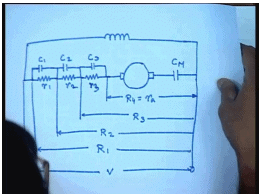
Thus this is the armature. There is a main contactor and of course, this sectional resistances. Each part can be shorted using contact, and the field coil is connected directly across this, and this is where the supply is given. This is the main contact. These are the housing, starting contacts c 1, c 2 and c 3. There are three sections of resistance r 1, r 2, r 3 given total resistance of all the resistances are in let us say the resistance is r 1. When c 1 is shorted the resistance becomes r 2; when c 2 is shorted resistance becomes r 3; when c 3 is shorted the resistance becomes r 4, which is nothing but the armature resistance of the machine.
Now in addition to this simple scheme, of course, many protection features like no load no volt release, over load protection, etcetera are also provided with commercial relay contactor based starter. So, when you push a start button, first the main contactor closes, and the machine starts accelerating. After certain time when the machine current falls below certain limit, the first contactor closes. The current immediately jumps and torque increases again; after sometime c 2 closes, after sometime c 3 closes so that the machine comes to full speed.
(Refer Slide Time: 39:13)
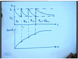
Pictorially the current and speed variation can be represented like this. This is the armature current I a, this is time, and let us say this is how the speed looks like. So, initially when machine is started the current jumps to a value I 1, the machine starts accelerating. As the machine accelerate the currents drop, and at this point let us say the first contactor c 1 is closed. And let us say by that time the current has dropped to a level of I 2. So, here the total armature circuit resistance was R 1. As soon as c 1 closes, the current again jumps back to I 1 and starts acceleration again. Here it will be R 2. Once current again falls back to I 2, c 2 is closed and current again jumps back to I 1.
So, here it is R 3. Finally, here the last contactor c 3 is closed. Initially the current jumps and then settles to its final value. This is how the armature current and the speed variation looks like in a sectional starter. This is R 4 equal to R a. Now how does one compute the values of the resistance to be inserted in the armature circuit? So, that the current wave forms during starting look like this; for that we note that the total resistance.
(Refer Slide Time: 42:12)
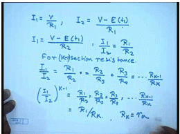
When the total resistance is R 1 then at start I 1 equal to V by R 1 at time 0. At time t 1 the current drops to value of I 2. So, I 2 equal to V minus E at t 1 divided by R 1, but at the same time we are shorting the contactor c 1, and the total resistance is becoming R 2. Since, the the back Emf depends only on the speed and speed cannot change instantaneously, we can also write I 1 equal to V minus E t 1 by R 2. Therefore, from here we have I 1 by I 2 equal to R 1 by R 2. And in the same manner if we continue for k section resistance we can induce that I 1 by I 2 equal to R 1 by R 2 into R 2 equal to R 2 by R 3 equal to R 3 by R 4 for k section resistance.
And finally, R k minus 1 by R k for k start that is k minus 1 section of external resistance. So, there are k such terms. So, I 1 by I 2 to the power k minus 1 equal to R 1 by R 2 into R 2 by R 3 into R 3 by R 4 into R k minus 1 by R k equal to, these things cancel; it becomes R 1 by R k. So, if there are k minus 1 external sections then R k is the last resistance that is equal to R a.
(Refer Slide Time: 45:57)
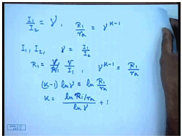
So, we have defined I 1 by I 2 equal to some gamma. Then R 1 by R a equal to gamma to the power k minus 1. So, the design process goes like this. First we choose given value of I 1 and I 2. Then we find value of gamma equal to I 1 by I 2. In order to restrict the starting current to a value of I 1 we choose R 1 to be equal to V by R 1. R 1 will be chosen as V by I 1. Now we know gamma to the power k minus 1 equal to R 1 by r a or K minus 1 ln gamma equal to ln R 1 by r a or k equal to ln R 1 by r a divided by ln gamma plus 1. So, that is how we find out the number of sections needed; of course, we have to make sure that we choose the nearest integer to what we get from this formula.
(Refer Slide Time: 48:07)
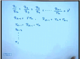
Once number of section has been chosen then of course, we are always find out the resistances from the relationship R 1 by R 2 equal to R 2 by R 3 equal to R 3 by R 4 equal to this way R k minus 1 by R k which is nothing but r a equal to gamma. So, R k minus 1 equal to gamma r a. So, the first sectional last sectional resistance can be found out which is R k minus 1 then equal to r a plus small r k minus 1. So, small r k minus 1 equal to R k minus 1 minus r a. This way we will continue till we find out all the resistance small r individual resistances. Let us try to explain this with the help of one problem.
(Refer Slide Time: 49:24)
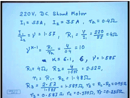
Let us say we need to design a starter for a 220 volt DC shunt machine. The maximum current I 1 should be limited to 55 amperes, and the minimum current during start 2 should be limited to 35 amperes. So, find out the number of sections and the resistances in each section? Let us say r a equal to 0.4 ohms. Then I 1 by I 2 equal to gamma equal to 1.57, and R 1 equal to V by I 1 equal to 220 by 55 equal to 4 ohm. Gamma to the power k minus 1 equal to R 1 by r a which is equal to 4 divided by 0.4 equal to 10.
Hence, N equal to k equal to 6.1 or the nearest integer is 6. So, it has to be a 6-step resistance. This modifies gamma to a value of 1.585. So, we have R 1 equal to 4 ohm, R 2 equal to 4 divided by 1.585 equal to 2.52 ohm. So, small r 1 equal to R 1 minus R 2 equal to 1.48 ohm. R 3 equal to 2.52 divided by 1.585 equal to 1.589 ohm. Hence, small r 2 equal to capital R 2 minus R 3 equal to 0.931 ohm. In the same manner we can proceed and find out r 3 equal to 0.587 ohm, r 4 equal to 0.370 ohm, and r 5 equal to 0.235 ohm. Instead of specifying the maximum and minimum limits of the currents, it is sometimes simpler to specify the number of steps, but there basically the same relations hold.
(Refer Slide Time: 53:30)
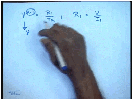
So, when the number of steps are specified we still have the basic relationship gamma to the power k minus 1 equal to R 1 by r a, and R 1 is still equal to V divided by I 1. So, the maximum current will be specified and the number of steps k minus 1 will be specified from which we have to first find out what should be gamma and then proceed in the same manner to calculate the different starting resistance sections.
Thank you.


