Braking of DC Shunt Motors
(Refer Slide Time: 00:32)

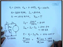
Let us solve 1 or 2 problems involving speed control of d c shunt motor, for example let us take a d c motor whose rated terminal voltage V t equal to 240 volts, the armature resistance equal to 0.04 ohm the intrinsic field resistance without any additional external resistance R f equal to 100 ohm this motor runs at a speed of N equal to 1200 RPM while taking a load current of 200 ampere from the supply.
Suppose we want to increase the speed to 1500 RPM how much additional resistance R F E is needed for this let us try to solve this problem. So, this is the arrangement this is shunt motor, this I l 200 amperes supply voltage is 240 volts therefore, I f equal to 240 volts by 100 ohm equal to 2.4 ampere I a equal to I l minus I f equal to 200 minus 2.4 equal to 187.6 amperes now the back E m f E equal to V t minus I a R a since at 1200 RPM and 1500 RPM V t and I a remains same then E also remains same. So, this E comes to 230 6.077 volts and remains constant, so but E at 1200 RPM divided by E at 1500 RPM is equal to field flux at 1200 RPM into by field flux at 1500 RPM that by 1200 by 1500, but we know that these 2 E are same.
(Refer Slide Time: 05:24)
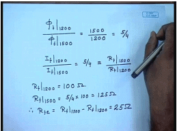
So, this is equal to 1 hence field flux at 1200 RPM divided by field flux at 1500 RPM is equal to 1500 by 1200 is equal to 5 by 4, but field flux is proportional assuming linear magnetic circuit. So, field current at 1200 RPM and field current at 1500 RPM this should be equal to 5 by four, but field currents are inversely proportional to the field resistance with constant supply voltage. So, this is also equal to total field circuit resistance at 1500 RPM divided by field circuit resistance at 1200 RPM, but we know at 1200 RPM no additional field resistance has been included. So, R f 1200 equal to hundred ohm hence R f at 1500 RPM should be 5 by 4 into 100 equal to hundred twenty 5 ohm later on additional resistance R f E equal to R f 1500 minus R f 1200 equal to twenty 5 ohm.
So, we need to insert a twenty 5 ohm resistance in the field circuit in order to increase the speed from 1200 RPM to 1500 RPM while the load current drawn by the motor is 200 ampere, now suppose the load current reduces to hundred ampere what happens to the speed with this additional resistance in circuit.
(Refer Slide Time: 08:07)
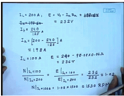
So, at I l equal to 200 amperes E is equal to V t minus I a R a I a equal to 197.6 amperes I f equal to 240 by 125 amperes minus. So, I a equal to 200 minus 240 by 125 amperes is approximately equal to 198 amperes. So, E is approximately equal to 197.6 volts and E I when I l equal to hundred ampere E is 98.08 into 0.04 ohm this comes to approximately equal to I am sorry this comes to approximately equal to 232 volts this comes approximately equal to 236 volts. So, since the field flux is same N at I l equal to hundred divided by N at I l equal to 200 is equal to E at I l equal to 100 divided by E at I l equal to 200 this is equal to 236 by 232 approximately equal to 1.02.
So, N at I l equal to 100 ampere equal to 1.02 into 1500 approximately equal to 1530 RPM. So, there will be a 30 RPM increase in speed if the load current decreases from 200 ampere to 100 amperes. So, another thing you observe that with field control the speed regulation is rather poor even for half load reduction there is a change in 30 RPM of speed which is not desirable where tight regulation of the motor speed is required. Now, let us try to solve another problem regarding the ward Leonard method of speed control for this.
(Refer Slide Time: 13:30)
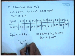
Let us say we have a ward Leonard system of speed control with the following rating there are 2 identical d c machines both are the following rating V t equal to 230 volts the power rating is 4 point 5 kilowatt rated speed is 1500 RPM the armature resistance of both machines are zero point 5 ohm the magnetization characteristics of the machines at 1500 RPM are as follows at no field current. There is a residual voltage of 45 volts 0.2 ampere that is 110 volts 0.3amperes hundred forty eight volts 0.4 amperes 175 volts zero point 5 amperes 1 ninety 5 volts 0.6 amperes 212 volts 0.723 volts 0.8230 volts and 1.0241 volts.
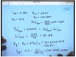
Now, the I f m is set at 0.8 amperes the motor speed has to be changed between 300 RPM N motor and 1500 RPM, where the whole range the output power of the motor will be 4 point 5 kilowatt. So, what should be the range of generator field current. So, from this data when I f m equal to 0.8 ampere.
(Refer Slide Time: 17:10)
The induced voltage induced E of the motor is from the o c c data, which is 2 thirty volts and. So, for motor speed N m equal to 300 RPM this is at N m equal to 1500 RPM or at N m equal to 300 RPM E m at 300 RPM will be 300 by 1500 into 2 thirty equal to forty 6 volts. The power output p m at 300 RPM equal to forty 5 hundred watts. So, this is equal to E m at 300 RPM multiplied by I a at 300 R p m. So, I a at 300 RPM is forty 5 zero zero by forty 6, which is equal to 97.8 amperes. So, what is the generator voltage E g equal to E of motor plus drop across both the armature resistance of the motor and the generator. So, 2 times R a I a this comes to forty 6 plus 2 into 0.5 into 97.8 this gives about 143.8 volts.
Now, from the magnetization data we see that at point 2 ampere of field current the generated voltage is hundred ten volt and at point 3 it is hundred forty eight volts. So, in order to generate a voltage of 1 forty there point eight volts somewhere close to zero point 3 ampere of field current will be required and this can be found by interpolation. So, the field current required I f g will be equal to it will be less than zero point 3 ampere minus 0.1 divided by 148 minus hundred ten 0.1 is the difference between this field current and this field current into 1 forty eight minus 143.8 this is equal to 0.29 amperes.
(Refer Slide Time: 21:24)
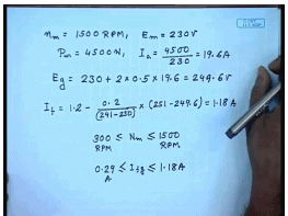
Similarly, for N m equal to 1500 RPM E m in that case we know equal to 2 thirty volts. So, p m equal to 4500 watts. So, I a equal to 4500 by 230 equal to 19.6 amperes. So, E generator equal to 230 plus 2 into resistance of the armature which is zero point 5 ohm into nineteen point 6 this is equal to 240 9.6 volts now again from the magnetization characteristics we find I f the missing data which says are 1 point 2 ampere this is 251 volts. So, point minus 0.2 divided by assuming linear this equal to hence for 300 I f g will vary in the range is 0.29 to 1.18 ampere. So, this is how we can calculate the field current required from the generator of a ward leonard system for controlling the speed of the motor over a given range. So, far we have concerned our self with starting and speed control of a d c shunt motor; however, the stopping of the motor is also equally important. So, let us see a few cases where this stopping becomes controlled stopping becomes very important.
(Refer Slide Time: 25:35)
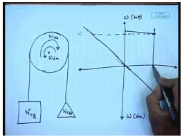
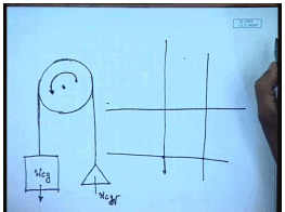
Let us go back to the situation of the lift or elevator drive, where as we have mentioned that is this elevator cage the weight of w c g and then there is a counter weight of w c c c w in order to lift the cage the this is omega for upward motion and this is omega for downward motion. So, the motor shaft needs to rotate in 2 different directions now let us see what happens under different operative scenario this is for upward motion this is for downward motion suppose the cage is full. So, that w c g is larger than w c and we want to lift the cage in that case we have seen that the torque speed characteristics of these machine this system is given by a vertical straight line and if it is driven by a separately excited d c machine then somewhere here the operating speed will be.
However, as the destination approaches it is necessary to stop the machine, but there was already some speed of the motor and speed of the system. So, the stored current energy has to be dissipated. So, it is necessary to apply certain braking torque. So, that the motor speed comes to stand still that is for some time the motor should be allowed to decelerate this is achieved by what is called dynamic braking in which case the terminal voltage of the motor is made 0, and the additional resistance is inserted hence the motor characteristics becomes somewhat like this and when you go to that then the operating characteristics shifts to here.
(Refer Slide Time: 29:24)
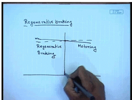
So, in addition to the load torque a amount of braking torque is applied, which quickly stops the system this is 1 situation another situation may arise where in this case suppose I am trying to lift a empty cage previously I was lifting a full cage, now I am trying to lift a empty cage now since now w c g is much lower than w c w the torque speed characteristics of the load will now shift to will become negative will go in this direction now the same motor torque speed characteristics is the same applied voltage it will remain the same. Now we see that the operating point shifts to second quadrant that is the motor now machine now acts as a generator and produces generating torque.
The machine runs at a speed somewhat higher than it is no load speed and feeds power back to the supply this is called the regenerative braking mode of operation it should be noted that the regenerative machine mode of braking the motor will normally run at a speed higher than the rated no load speed. Hence, it is not possible for the regenerative braking mode of operation to bring the motor to a standstill it will continue to run at a speed higher than the rated no load speed until and unless of course. The arrangement is brought made to bring the applied armature voltage reduce the applied armature voltage gradually to zero in which case even regenerative braking method can be used for stopping the system.
(Refer Slide Time: 32:36)
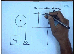
A third situation will arise, suppose we are trying to lower a full cage the direction of rotation will now be this; however, it is necessary to lower the cage since w c g is now larger than w c w the load torque is in this quadrant; however, now the motor rotates in the reverse direction and it is necessary now to it is now necessary to control the speed in which case what we do we reverse the terminal supply and make the motor operate in this fashion. So, this becomes the supply voltage.
(Refer Slide Time: 34:45)
So, there are different methods of braking a d c shunt generator in which 1 case we found that this is called the regenerative braking here the load tries to drive the motor at a speed higher than the no load speed this is motoring, and this is the regenerative braking mode of operation at a speed higher than the rated no load speed of the machine. So, the motor works as a generator and hence a opposing or a braking torque is generated which tends to limit the speed of the machine it should be remembered that regenerative braking cannot be used for stopping the machine.
(Refer Slide Time: 36:18)
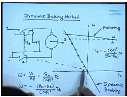
The other braking method or stopping method is called the dynamic braking method in this case the motor is disconnected from the supply and then connected to an external braking resistance. So, again the motor acts as a generator and the kinetic energy stored in the motor and load system is dissipated in this resistance and let us say that while motoring it was operating on it is normal torque speed characteristics at a speed of omega and in order to apply regenerative braking we disconnect the machine from the supply hence the applied terminal voltage becomes zero in addition we put a additional braking resistance R b. So, the characteristics now becomes a straight line passing through the origin the slope of which is determined by the braking resistance R b.
So, as soon as dynamic braking this is motoring characteristics this is dynamic braking characteristics the motor torque speed characteristics is omega equal to V t by k phi minus R a divided by k phi square t E the motoring mode V t was equal to V t rated and R a was equal to armature resistance of the machine, and this was the characteristics during regenerative braking V t is made zero then the characteristics, becomes minus R a plus and an additional resistance R b is added R b by k phi square t e.
So, as the speed goes down or in other words the torque generated by the machine becomes minus k phi square by R a plus R b into omega. So, as soon as regenerative braking is applied the operating point shifts from point a to point b hence the speed of the machine cannot change abruptly and then it follows the regenerative braking characteristics and comes to stand still. So, this is called the regenerative method of braking in this case the motor can be made to stop completely by electrical braking method, but it cannot recover the stored energy in the machine and the load back. So, this energy is wasted in a braking resistance. It is important to add a additional braking resistance because otherwise the current during regenerative braking can be very large as much as much as the almost the starting current with direct online starting which is not desirable therefore, a additional braking resistance is normally included
(Refer Slide Time: 42:06)
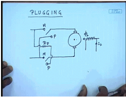
There is a third method of braking called plugging in this case what we do it is somewhat like dynamic braking, but this is the position of the switch for motor mode operation this is the position of the switch for plugging mode operation. So, what we in essence are doing is in order to apply plugging you disconnect the machine from the normal supply and reverse the polarity of the supply voltage this of course, essential that a additional resistance is inserted into the motor terminal. So, what will be the characteristics.
(Refer Slide Time: 44:15)
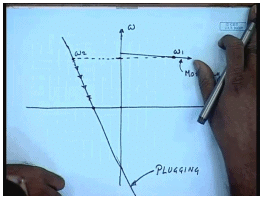
So, this was the nominal torque speed characteristics of the motor, and suppose it was operating at this speed of omega 1 when we apply plugging the polarity omega equal to V t by k phi minus R a by k phi square t E or plugging the polarity of V t is made negative as well as R a increases to R a plus R p.
So, for plugging the characteristics becomes somewhat like this and as soon as plugging is applied the operating point shifts to omega 2 and then follows the this is the motoring mode and this is the plugging and then follows the characteristics during plugging to come to zero speed; however, it is to be understood that if we apply plugging then the motor can be can have a larger braking torque, but it does not stop at zero speed rather it tends to start rotating in the reverse direction therefore, before the motor come to a standstill it must be disconnected from the supply otherwise the motor may start rotating in the reverse direction.
(Refer Slide Time: 47:37)
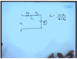
Another thing to note is that during plugging the polarity of the as long as the speed remains positive the equivalent circuit of the motor becomes somewhat like this. This is the plugging resistance this is the armature resistance and this is the induced back E m f the polarity of the supplied voltage as now reversed this becomes plus this becomes minus V t E the current I a now flows out of the machine I a equal to V t plus E a divided by R a plus R p. So, not only does the power supplied by the internal back E m f E p, but as well as the power additional power is taken from the source which is also dissipated in the armature and the plugging resistance. So, this method of stopping the motor is very inefficient, and is not used except for very small motors, let us try to get an idea of the kind of power loss that is involved by solving a small problem.
(Refer Slide Time: 49:40)
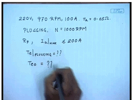
For that let us assume that we have a d c shunt motor rating is 2 twenty volts nine seventy RPM thousand hundred amperes the armature resistance R a equal to 0.05 ohm suppose we want to break it by using plugging from a initial RPM of thousand R p m. So, find out what should be R p. So, that I a maximum is less than 2 times the rated armature current once, it is less than 200 amperes then what is the braking torque and what is the torque at 0 speed.
(Refer Slide Time: 51:30)
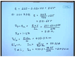
Now, at nine seventy RPM we know at rated current E equal to 2 twenty minus zero point zero 5 into hundred equal to 215 volts. So, at thousand RPM E equal to thousand by nine seventy into 215 equal to 2 twenty 1 point 6 5 volts. So, if I want to restrict the current to 200 ampere then R p plus R a equal to E plus V divided by I a this is equal to 221.65 plus 220 by 200 this is equal to 2.21 ohm hence R p will be 1 point 1 6 ohm.
The braking torque t t E plugging equal to E into I a by omega this comes to 4 twenty 3 point 3 newton meter. So, very large torque at 0 speed E equal to zero. So, I a equal to V divided by R p plus R a this comes to 99.55 amperes and since t is proportional to I a t E that is zero will be equal to 423.3 into ninety nine point 5 five by 200 this comes to 200 ten point seven newton meter. So, we see even at start there is a very large torque and there will be a tendency of the motor to start rotating in the reverse direction hence the motor must be disconnected before the speed comes to zero.
Thank you.