
Best Study Material for Electrical Engineering (EE) Exam
Electrical Engineering (EE) Exam > Electrical Engineering (EE) Notes > Lecture 4 - Introduction to Digital Control
Lecture 4 - Introduction to Digital Control - Electrical Engineering (EE) PDF Download
Lecture 4 - Introduction to Digital Control, Control Systems
1 Data Reconstruction
Most of the control systems have analog controlled processes which are inherently driven by analog inputs. Thus the outputs of a digital controller should first be converted into analog signals before being applied to the systems. Another way to look at the problem is that the high frequency components of f (t) should be removed before applying to analog devices. A low pass filter or a data reconstruction device is necessary to perform this operation.
In control system, hold operation becomes the most popular way of reconstruction due to its simplicity and low cost. Problem of data reconstruction can be formulated as: “
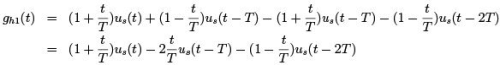
Given a sequence of numbers, f (0), f (T ), f (2T ), · · · , f (kt), · · · , a continuous time signal f (t), t ≥ 0, is to be reconstructed from the information contained in the sequence.” Data reconstruction process may be regarded as an extrapolation process since the continuous data signal has to be formed based on the information available at past sampling instants.
Suppose the original signal f (t) between two consecutive sampling instants kT and (k + 1)T is to be estimated based on the values of f (t) at previous instants of kT , i.e., (k − 1)T , (k − 2)T , · · · 0.
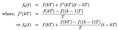
Power series expansion is a well known method of generating the desired approximation which yields
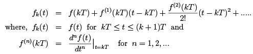
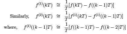
Since the only available informadttionn a tb=okTut ff(otr) nis =its1,m2a, .g.n. itude at the sampling instants, the derivatives of f (t) must be estimated from the values of f (kT ), as
1.1 Zero Order
Hold Higher the order of the derivatives to be estimated is, larger will be the number of delayed pulses required. Since time delay degrades the stability of a closed loop control system, using higher order derivatives of f (t) for more accurate reconstruction often causes serious stability problem. Moreover a high order extrapolation requires complex circuitry and results in high cost.
For the above reasons, use of only the first term in the power series to approximate f (t) during the time interval kT ≤ t < (k + 1)T is very popular and the device for this type of extrapolation is known as zero-order extrapolator or zero order hold. It holds the value of f (kT ) for kT ≤ t < (k + 1)T until the next sample f ((k + 1)T ) arrives. Figure 1 illustrates the operation of a ZOH where the green line represents the original continuous signal and brown line represents the reconstructed signal from ZOH.
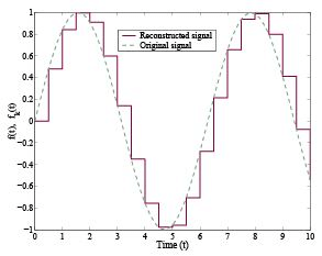
Figure 1: Zero order hold operation
The accuracy of zero order hold (ZOH) depends on the sampling frequency. When T → 0, the output of ZOH approaches the continuous time signal. Zero order hold is again a linear device which satisfies the principle of superposition.
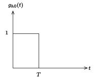
Figure 2: Impulse response of ZOH
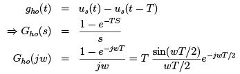
The impulse response of a ZOH, as shown in Figure 2, can be written as
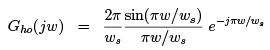
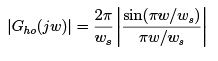
Magnitude of Gho(j w):
Phase of Gho(j w):
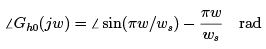
The sign of ∠ sin(πw/ws) changes at every integral value of  . The change of sign from + to − can be regarded as a phase change of −1800. Thus the phase characteristics of ZOH is linear with jump discontinuities of −1800 at integral multiple of ws. The magnitude and phase characteristics of ZOH are shown in Figure 3.
At the cut off frequency  , magnitude is 0.636. When compared with an ideal low pass filter, we see that instead of cutting of sharply at w =
  , the amplitude characteristics of Gho(j w) is zero atand integral multiples of ws.
1.2 First Order
Hold When the 1st two terms of the power series are used to extrapolate f (t), over the time interval kT < t < (k + 1)T , the device is called a first order hold (FOH). Thus
Impulse response of FOH is obtained by applying a unit impulse at t = 0, the corresponding output is obtained by setting k = 0, 1, 2, .....
for k = 0, when 0 ≤ t < T , 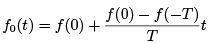
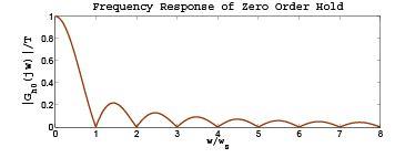
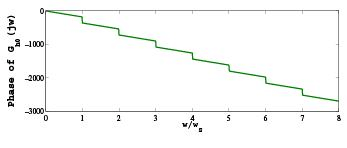
Figure 3: Frequency response of ZOH
f (0) = 1 [impulse unit] f (−T ) = 0 fh1(t) =  in this region. When T ≤ t < 2T
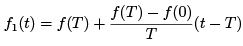
Since, f (T ) = 0 and f (0) = 1, fh1(t) =  in this region. fh1 (t) is 0 for t ≥ 2T , since f (t) = 0 for t ≥ 2T .
Figure 4 shows the impulse response of first order hold.
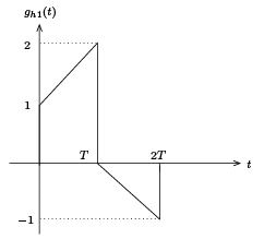
Figure 4: Impulse response of First Order Hold
If we combine all three regions, we can write the impulse response of a first order hold as,
One can verify that according to the above expression, when 0 ≤ t < T , only the first term produces a nonzero value which is nothing but (1 + t/T ). Similarly, when T ≤ t < 2T , first two terms produce non zero values and the resultant is (1 − t/T ). In case of t ≥ 2T , all three terms produce nonzero values and the resultant is 0.
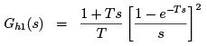
The transfer function of a first order hold is:
Frequency Response
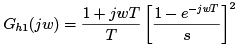
Magnitude:
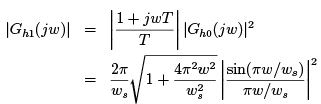
Phase:

The frequency response is shown in Figure 5.
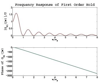
Figure 5: Frequency response of FOH
Figure 6 shows a comparison of the reconstructed outputs of ZOH and FOH.
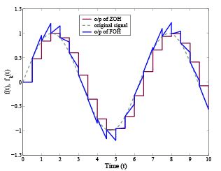
Figure 6: Operation of ZOH and FOH
The document Lecture 4 - Introduction to Digital Control - Electrical Engineering (EE) is a part of Electrical Engineering (EE) category.
All you need of Electrical Engineering (EE) at this link: Electrical Engineering (EE)


FAQs on Lecture 4 - Introduction to Digital Control - Electrical Engineering (EE)
| 1. What is digital control? |  |
| 2. What are the advantages of digital control over analog control? | |
Ans. Digital control offers several advantages over analog control. Firstly, it provides better accuracy and precision due to the ability to perform calculations with high resolution. Secondly, it allows for easy implementation of complex control algorithms and the ability to modify them without making hardware changes. Thirdly, it offers improved robustness and noise immunity, as digital signals are less susceptible to interference. Additionally, digital control enables the use of advanced techniques such as adaptive control and optimal control.
| 3. How does digital control differ from analog control? | |
Ans. Digital control differs from analog control in several aspects. Firstly, analog control uses continuous signals to represent variables, while digital control uses discrete signals. Secondly, analog control typically relies on analog components, such as op-amps and amplifiers, while digital control uses digital devices like microcontrollers or DSPs. Thirdly, analog control is limited in terms of complexity and flexibility compared to digital control, which can implement complex algorithms and adapt to changing conditions more easily.
| 4. What are the main components of a digital control system? | |
Ans. A digital control system consists of several main components. Firstly, it includes sensors that measure the system's output and provide feedback signals. Secondly, it requires a digital controller, which processes the measured signals and calculates control actions based on a control algorithm. Thirdly, it involves actuators that receive the control signals from the controller and physically manipulate the system. Additionally, it may include analog-to-digital converters (ADCs) and digital-to-analog converters (DACs) to convert between continuous and discrete signals.
| 5. How is stability achieved in digital control systems? | |
Ans. Stability in digital control systems is achieved by ensuring that the system's response does not grow indefinitely over time. This is typically done by designing the control algorithm to satisfy certain stability criteria, such as the Nyquist stability criterion or the Bode stability criterion. Additionally, techniques like pole placement and robust control can be used to ensure stability in the presence of uncertainties or disturbances. It is important to analyze the system's stability using tools such as the Z-transform or frequency response analysis.
About this Document

4.84/5
Rating

Mar 24, 2025
Last updated
Document Description: Lecture 4 - Introduction to Digital Control for Electrical Engineering (EE) 2025 is part of Electrical Engineering (EE) preparation. The notes and questions for Lecture 4 - Introduction to Digital Control have been prepared according to the Electrical Engineering (EE) exam syllabus. Information about Lecture 4 - Introduction to Digital Control covers topics like and Lecture 4 - Introduction to Digital Control Example, for Electrical Engineering (EE) 2025 Exam. Find important definitions, questions, notes, meanings, examples, exercises and tests below for Lecture 4 - Introduction to Digital Control.
Introduction of Lecture 4 - Introduction to Digital Control in English is available as part of
our Electrical Engineering (EE) preparation & Lecture 4 - Introduction to Digital Control in Hindi for Electrical Engineering (EE)
courses. Download more important topics, notes, lectures and mock test series for Electrical Engineering (EE)
Exam by signing up for free. Electrical Engineering (EE): Lecture 4 - Introduction to Digital Control - Electrical Engineering (EE)
Description
Full syllabus notes, lecture & questions for Lecture 4 - Introduction to Digital Control - Electrical Engineering (EE) - Electrical Engineering (EE) | Plus excerises question with solution to help you revise complete syllabus | Best notes, free PDF download
Information about Lecture 4 - Introduction to Digital Control
In this doc you can find the meaning of Lecture 4 - Introduction to Digital Control defined & explained in the simplest way possible.
Besides explaining types of Lecture 4 - Introduction to Digital Control theory,
EduRev gives you an ample number of questions to practice Lecture 4 - Introduction to Digital Control tests, examples and also practice Electrical Engineering (EE) tests.
Download as PDF
Top Courses for Electrical Engineering (EE)

Related Searches
Objective type Questions
,Semester Notes
,Free
,Previous Year Questions with Solutions
,Viva Questions
,Exam
,ppt
,Important questions
,MCQs
,Sample Paper
,mock tests for examination
,practice quizzes
,shortcuts and tricks
,Lecture 4 - Introduction to Digital Control - Electrical Engineering (EE)
,Lecture 4 - Introduction to Digital Control - Electrical Engineering (EE)
,Summary
,Extra Questions
,Lecture 4 - Introduction to Digital Control - Electrical Engineering (EE)
,past year papers
,study material
,video lectures
;


Additional Information about Lecture 4 - Introduction to Digital Control for Electrical Engineering (EE) Preparation
Lecture 4 - Introduction to Digital Control Free PDF Download
The Lecture 4 - Introduction to Digital Control is an invaluable resource that delves deep into the core of the Electrical Engineering (EE) exam.
These study notes are curated by experts and cover all the essential topics and concepts, making your preparation more efficient and effective.
With the help of these notes, you can grasp complex subjects quickly, revise important points easily,
and reinforce your understanding of key concepts. The study notes are presented in a concise and easy-to-understand manner,
allowing you to optimize your learning process. Whether you're looking for best-recommended books, sample papers, study material,
or toppers' notes, this PDF has got you covered. Download the Lecture 4 - Introduction to Digital Control now and kickstart your journey towards success in the Electrical Engineering (EE) exam.
Importance of Lecture 4 - Introduction to Digital Control
The importance of Lecture 4 - Introduction to Digital Control cannot be overstated, especially for Electrical Engineering (EE) aspirants.
This document holds the key to success in the Electrical Engineering (EE) exam.
It offers a detailed understanding of the concept, providing invaluable insights into the topic.
By knowing the concepts well in advance, students can plan their preparation effectively.
Utilize this indispensable guide for a well-rounded preparation and achieve your desired results.
Lecture 4 - Introduction to Digital Control Notes
Lecture 4 - Introduction to Digital Control Notes offer in-depth insights into the specific topic to help you master it with ease.
This comprehensive document covers all aspects related to Lecture 4 - Introduction to Digital Control.
It includes detailed information about the exam syllabus, recommended books, and study materials for a well-rounded preparation.
Practice papers and question papers enable you to assess your progress effectively.
Additionally, the paper analysis provides valuable tips for tackling the exam strategically.
Access to Toppers' notes gives you an edge in understanding complex concepts.
Whether you're a beginner or aiming for advanced proficiency, Lecture 4 - Introduction to Digital Control Notes on EduRev are your ultimate resource for success.
Lecture 4 - Introduction to Digital Control Electrical Engineering (EE) Questions
The "Lecture 4 - Introduction to Digital Control Electrical Engineering (EE) Questions" guide is a valuable resource for all aspiring students preparing for the
Electrical Engineering (EE) exam. It focuses on providing a wide range of practice questions to help students gauge
their understanding of the exam topics. These questions cover the entire syllabus, ensuring comprehensive preparation.
The guide includes previous years' question papers for students to familiarize themselves with the exam's format and difficulty level.
Additionally, it offers subject-specific question banks, allowing students to focus on weak areas and improve their performance.
Study Lecture 4 - Introduction to Digital Control on the App
Students of Electrical Engineering (EE) can study Lecture 4 - Introduction to Digital Control alongwith tests & analysis from the EduRev app,
which will help them while preparing for their exam. Apart from the Lecture 4 - Introduction to Digital Control,
students can also utilize the EduRev App for other study materials such as previous year question papers, syllabus, important questions, etc.
The EduRev App will make your learning easier as you can access it from anywhere you want.
The content of Lecture 4 - Introduction to Digital Control is prepared as per the latest Electrical Engineering (EE) syllabus.
|
© EduRev
|
Education Revolution
|


|


Signup to see your scores
go up
within 7 days!
within 7 days!
Takes less than 10 seconds to signup