Lecture 21 - Lag lead Compensator - Electrical Engineering (EE) PDF Download

Lecture 21 - Lag-lead Compensator, Control Systems
1 Lag-lead Compensator
When a single lead or lag compensator cannot guarantee the specified design criteria, a laglead compensator is used.
In lag-lead compensator the lag part precedes the lead part. A continuous time lag-lead compensator is given by
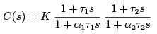 where, α1 > 1, α2 < 1
The corner frequencies are  The frequency response is shown in Figure 1.
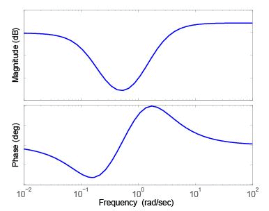
Figure 1: Frequency response of a lag-lead compensator
In a nutshell,
- If it is not specified which type of compensator has to be designed, one should first check the PM and BW of the uncompensated system with adjustable gain K .
- If the BW is smaller than the acceptable BW one may go for lead compensator. If the BW is large, lead compensator may not be useful since it provides high frequency amplification.
- One may go for a lag compensator when BW is large provided the open loop system is stable.
- If the lag compensator results in a too low BW (slow speed of response), a lag-lead compensator may be used.
1.1 Lag-lead compensator design
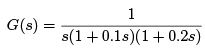
Consider the following system with transfer function
Design a lag-lead compensator C (s) such that the phase margin of the compensated system is at least 45o at gain crossover frequency around 10 rad/sec and the velocity error constant Kv is 30.
The lag-lead compensator is given by
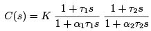 where, α1 > 1, α2 < 1
When s → 0, C (s) → K .
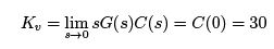
Thus K = 30. Bode plot of the modified system K G(s) is shown in Figure 2. The gain crossover frequency and phase margin of K G(s) are found out to be 9.77 rad/sec and −17.2o respectively.
Since the PM of the uncompensated system with K is negative, we need a lead compensator to compensate for the negative PM and achieve the desired phase margin.
However, we know that introduction of a lead compensator will eventually increase the gain crossover frequency to maintain the low frequency gain.
Thus the gain crossover frequency of the system cascaded with a lead compensator is likely to be much above the specified one, since the gain crossover frequency of the uncompensated
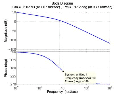
Figure 2: Frequency response of the uncompensated system of Example 1 system with K is already 9.77 rad/sec.
Thus a lag-lead compensator is required to compensate for both.
We design the lead part first.
From Figure 2, it is seen that at 10 rad/sec the phase angle of the system is −198o.
Since the new ωg should be 10 rad/sec, the required additional phase at ωg , to maintain the specified PM, is 45 − (180 − 198) = 63o. With safety margin 2o,
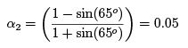
And

which gives τ2 = 0.45. However, introducing this compensator will actually increase the gain crossover frequency where the phase characteristic will be different than the designed one.
This can be seen from Figure 3.
The gain crossover frequency is increased to 23.2 rad/sec. At 10 rad/sec, the phase angle is −134o and gain is 12.6 dB. To make this as the actual gain crossover frequency, lag part
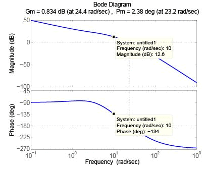
Figure 3: Frequency response of the system in Example 1 with only a lead compensator should provide an attenuation of −12.6 dB at high frequencies.
At high frequencies the magnitude of the lag compensator part is 1/α1. Thus ,
20 log10 α1 = 12.6
which gives α1 = 4.27. Now, 1/τ1 should be placed much below the new gain crossover frequency to retain the desired PM. Let 1/τ1 be 0.25. Thus
τ1 = 4
The overall compensator is
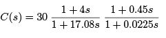
The frequency response of the system after introducing the above compensator is shown in Figure 4, which shows that the desired performance criteria are met.
Example 2:
Now let us consider that the system as described in the previous example is sub ject to a

Figure 4: Frequency response of the system in Example 1 with a lag-lead compensator sampled data control system with sampling time T = 0.1 sec. We would use MATLAB to derive the plant transfer function w-plane.
Use the below commands.
>> s=tf(’s’);
>> gc=1/(s*(1+0.1*s)*(1+0.2*s));
>> gz=c2d(gc,0.1,’zoh’);
You would get
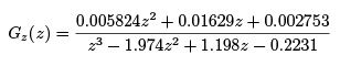
The bi-linear transformation
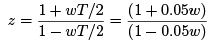
will transfer Gz (z) into w-plane. Use the below commands
>> aug=[0.1,1];
>> gwss = bilin(ss(gz),-1,’S_Tust’,aug)
>> gw=tf(gwss)
to find out the transfer function in w-plane, as
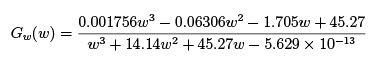
Since the velocity error constant criterion will produce the same controller dcgain K , the gain of the lag-lead compensator is designed to be 30.
The Bode plot of the uncompensated system with K = 30 is shown in Figure 5.
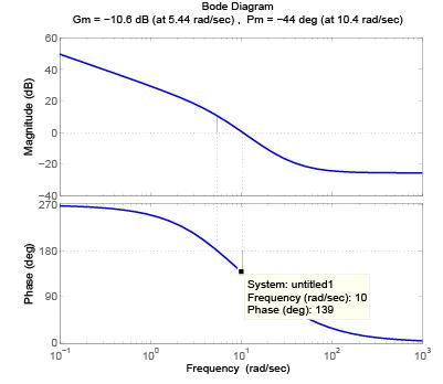
Figure 5: Bode plot of the uncompensated system for Example 2
From Figure 5, it is seen that at 10 rad/sec the phase angle of the system is 139 = −221o.
Thus a huge phase lead (86o) is required if we want to acieve a PM of 45o which is not possible with a single lead compensator. Let us lower the PM requirement to a minimum of 20o at ωg = 10 rad/sec.
Since the new ωg should be 10 rad/sec, the required additional phase at ωg , to maintain the specified PM, is 20 − (180 − 221) = 61o. With safety margin 5o,
And

which gives τ2 = 0.47. However, introducing this compensator will actually increase the gain crossover frequency where the phase characteristic will be different than the designed one.
This can be seen from Figure 6.
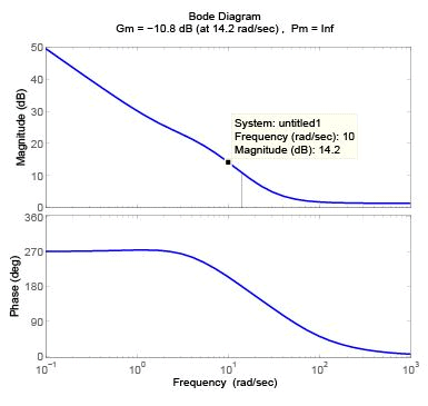
Figure 6: Frequency response of the system in Example 2 with only a lead compensator
Also, as seen from Figure 6, the GM of the system is negative. Thus we need a lag compensator to lower the magnitude at 10 rad/sec. At 10 rad/sec, the magnitude is 14.2 dB.
To make this as the actual gain crossover frequency, lag part should provide an attenuation of −14.2 dB at high frequencies.
Thus,
20 log10 α1 = 14.2
which gives α1 = 5.11. Now, 1/τ1 should be placed much below the new gain crossover frequency to retain the desired PM. Let 1/τ1 be 10/10 = 1. Thus
τ1 = 1
The overall compensator is
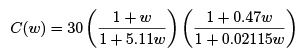
The frequency response of the system after introducing the above compensator is shown in Figure 7, which shows that the desired performance criteria are met.

Figure 7: Frequency response of the system in Example 2 with a lag-lead compensator
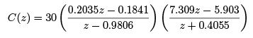
Re-converting the controller in z-domain, we get
FAQs on Lecture 21 - Lag lead Compensator - Electrical Engineering (EE)
| 1. What is a lag lead compensator? |  |
| 2. How does a lag lead compensator work? | |
| 3. When is a lag lead compensator used? | |
| 4. How is a lag lead compensator designed? | |
| 5. What are the advantages of using a lag lead compensator? | |


Top Courses for Electrical Engineering (EE)

MCQs
,Important questions
,Exam
,practice quizzes
,Sample Paper
,study material
,Lecture 21 - Lag lead Compensator - Electrical Engineering (EE)
,past year papers
,Lecture 21 - Lag lead Compensator - Electrical Engineering (EE)
,Free
,Viva Questions
,shortcuts and tricks
,video lectures
,mock tests for examination
,Previous Year Questions with Solutions
,Lecture 21 - Lag lead Compensator - Electrical Engineering (EE)
,Summary
,ppt
,Objective type Questions
,Extra Questions
,Semester Notes
;


Lecture 21 - Lag lead Compensator Free PDF Download
Importance of Lecture 21 - Lag lead Compensator
Lecture 21 - Lag lead Compensator Notes
Lecture 21 - Lag lead Compensator Electrical Engineering (EE) Questions
Study Lecture 21 - Lag lead Compensator on the App
|
© EduRev
|
Education Revolution
|


|


within 7 days!