Study of DC Transients in R-L & R-C Circuits - 3 - Electrical Engineering (EE) PDF Download

Discharging of a capacitor or Fall of a capacitor voltage in dc circuits
Fig. 10.17(b) shows that the switch ‘S’ is closed at position ‘1’ for sufficiently long time and the circuit has reached in steady-state condition. At ‘ t = 0’ the switch’ S ’ is opened and kept in position ‘2’ and remains there. Our job is to find the expressions for (i) voltage across the capacitor (vc) (ii) voltage across the resistance (vR) (iii) current (i (t)) through the capacitor (discharging current) (iv) discharge of charge (q(t)) through the circuit.
Solution: For t < 0, the switch ‘S’ in position 1. The capacitor acts like an open circuit to dc, but the voltage across the capacitor is same as the supply voltage VS. Since, the capacitor voltage cannot change instantaneously, this implies that vc (0-) = vc (0+) = Vs
When the switch is closed in position ‘2’, the current i(t) will flow through the circuit until capacitor is completely discharged through the resistance R. In other words, the discharging cycle will start at t = 0. Now applying KVL around the loop, we get
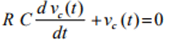
The solution of input free differential equation (10.49) is given by
vc (t) = A1eαt
where the value of α is obtained from the characteristic equation and it is equal to  The constant A1 is obtained using the initial condition of the circuit in Eq.(10.50). Note, at ‘t = 0’ (when the switch is just closed in position ‘2’) the voltage across the capacitor vc (t) = Vs. Using this condition in Eq.(10.50), we get
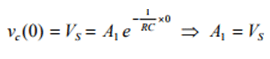
Now the following expressions are written as
Voltage across the capacitance 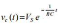
Voltage across the resistance 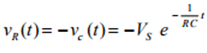
Voltage across the resistance 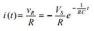
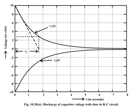
An inspection of the above exponential terms of equations from (10.51) to (10.53) reveals that the time constant of RC circuit is given by τ = RC (sec.)
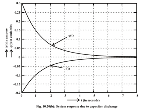
This means that at time t =τ , the capacitor’s voltage vc drops to 36.8% of its initial value (see fig. 10.20(a)). For all practical purposes, the dc transient is considered to end after a time span of 5 τ . At such time steady state condition is said to be reached. Plots of above equations as a function of time are depicted in fig. 10.20(a) and fig. 10.20(b) respectively.
Energy stored in a capacitor
The ideal capacitor does not dissipate any of the energy supplied by the source. It stores energy in the form of an electric field between the conducting plates. Let us consider a voltage source VS is connected to a series R - C circuit and it is assumed that
the capacitor is initially uncharged. The capacitor voltage (vc(t)) and current (ic(t)) waveforms during the charging period are shown in fig.10.21 (see the expressions (10.45) and (10.47)) and instantaneous power (pc (t) = vc(t)xi(t)) supplied to the capacitor is also shown in the same figure.
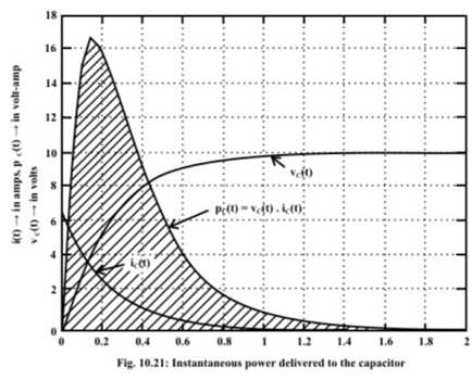
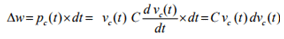
Let us consider the instantaneous power supplied to the capacitor is given by
Pc (t) = Vc (t) X i(t)
Now, the energy supplied to the capacitor in dt second is given by
Total energy supplied to the capacitor in t seconds is expressed as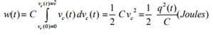
(Note initial voltage across capacitor is zero and q(t)t is the charge accumulated on each plate at a time t) .
When the capacitor is fully charged, its terminal voltage is equal to the source voltage Vs. The amount of energy stored in capacitor in the form of electric field is given by
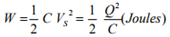
where Q is the final charge accumulated on each plate of the capacitor at steady state ( i.e., t → ∞) i.e., when the capacitor is fully charged.
Example: L.10.6 The switch ‘S’ shown in fig.L.10.22 is kept open for a long time and then it is closed at time 

(vi) find the time constants of the circuit before and after the switch is closed

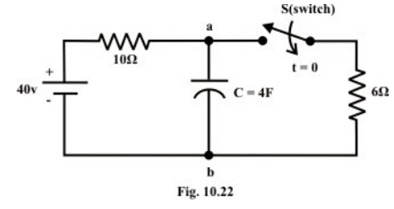
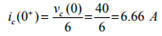
Solution: As we know the voltage across the capacitor vc (t) cannot change instantaneously due to the principle of conservation of charge. Therefore, the voltage across the capacitor just before the switch is closed vc (0-) = voltage across the capacitor just after the switch is closed vc (0+) = 40 V (note the terminal ‘a’ is positively charged. It may be noted that the capacitor current before the switch ‘ S’ is closed is ic (0-) = 0A.. On the other hand, at t = 0, the current through 10 Ω resistor is zero but the current through capacitor can be computed as
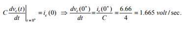
(note, voltage across the capacitor cannot change instantaneously at instant of switching). The rate of change of capacitor voltage at time ‘t = 0’ is expressed as
Time constant of the circuit before the switch was closed 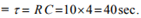 Time constant of the circuit after the switch is closed is
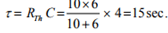
(replace the part of the circuit than contains only independent sources and resistive elements by an equivalent Thevenin’s voltage source. In this case, we need only to find the Thevenin resistance RTh).
Note: When the switch is kept in closed position, initially the capacitor will be in discharge state and subsequently its voltage will decrease with the increase in time. Finally, at steady state the capacitor is charged with a voltage 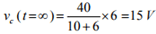 (theoretically, time required to reach the capacitor voltage at steady value is
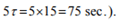
Example: The circuit shown in Fig.10.23 has been established for a long time. The switch is closed at time t = 0 . Find the current (i) 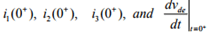 (ii) at steady state the voltage across the capacitors,
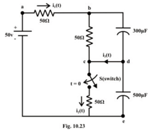
Solution: (i) At t = 0- no current flowing through the circuit, so the voltage at points ‘b’ and ‘d’ are both equal to 50volt. When the switch ‘S’ closes the capacitor voltage remains constant and does not change its voltage instantaneously. The current i1(0+) through a - b branch must then equal to zero, since voltage at terminal ‘b’ is equal to vb (0+)= 50 volt., current through b - c is also zero. One can immediately find out the current through c − e equal
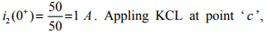
i3(0+) = 1 A which is the only current flow at t = 0+ around the loop ‘ d - c - e - d . Note the capacitor across ‘d - e’ branch acts as a voltage source, the change of capacitor
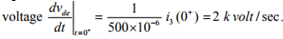
(ii) at steady state the voltage across each capacitor is given 
At steady state current delivered by the source to the different branches are given by

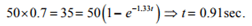
Example: The circuit shown in fig. 10.24(a) is switched on at time t = 0 . How long it takes for the capacitor to attain 70 % of its final voltage? Assume the capacitor is initially not charged. Find also the time constant (τ) of the circuit after the switch is closed.
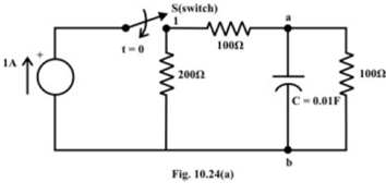
The circuit containing only resistive elements and independent current source (i.e., nontransient part of the circuit) is converted to an equivalent voltage source which is shown in fig.10.24(b).
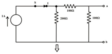
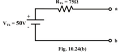
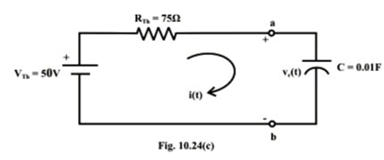
Fig.10.24(c) shows the capacitor C is connected across the Thevenin’s voltage terminals ‘a’ and ‘b’ in series with Thevenin’s resistance RTh .
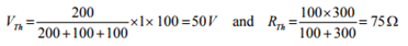
The parameters of Thevenin’s voltage source are computed below:
Using KVL around the closed path, one can find the current through the capacitor and hence, the voltage across the capacitor.
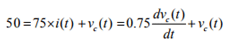
The solution of the differential equation is given by
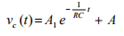
Using the initial and boundary conditions of the circuit, we obtain the final expression of voltage across the capacitor vc(t) as
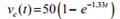
Let ‘t’ is the time required to reach the capacitor voltage 70% of its final (i.e., steady state) voltage.
Example: The switch ‘S’ of the circuit shown in fig.10.25(a) is closed at position ‘1’ at t = 0.
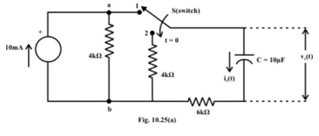
Find voltage vc(t) and current ic (t) expressions for t > 0 . Assume that the capacitor is initially fully uncharged (i.e., . vc (0) = 0).
(i) find the mathematical expressions for vc(t) and ic (t) if the switch ‘S’ is thrown into position ‘2’ at t = t (sec.) of the charging phase.
(ii) plot the waveforms obtained in parts (i) to (ii) on the same time axis for the voltage vc (t) and the current ic (t) using the identified polarity of voltage and current directions.
Solution: (i) The current source is converted to an equivalent voltage source and it is redrawn in fig.10.25(b) when the switch ‘ S ’ is in position ‘1’.
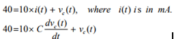
The voltage expression across the capacitor using the initial and boundary conditions of the circuit, one can write vc(t) as
Note that the time constant of the circuit in part (i) is τ = RC m =100 sec.
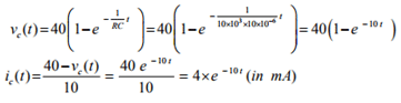
(ii) The switch ‘S’ is thrown into position ‘2’ at t =τ =0.1sec. and the corresponding circuit diagram is shown in fig.10.25(c).
Note, at time t = t = 0.1sec., the capacitor is charged with a voltage = vc(t = 0.1) = 40(1-e -10x0.1) = 40x0.632 = 25.28V and at the same time (t = t = 0.1sec.) the current in capacitor is 4 x e -10t = 4x 0.368 = 1.472 (in mA) . Considering the fig.10.25(c), one can write KVL around the closed path
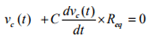
where Req = 4 + 6 =10kΩ and the capacitor is now in discharging phase.
The solution of Eq.(10.64) can be found using the initial and final voltage of the capacitor (initial voltage 
and it is given by 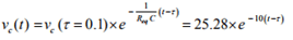
Discharging current expression is given by (note, current direction is just opposite to the assigned direction and it is taken into account with a –ve sign)
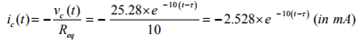
(Note, the above two expressions are valid only for t ≥ τ)
The circuit responses for charging and discharging phases in (i) and (ii) are shown in fig.10.25 (d).
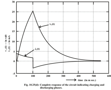
Remark-6 Note that the current through the capacitor (see fig. 10.25(d)) can change instantaneously like the voltage across the inductor.
Appendix-A
L.10.A Solution of nth order linear time invariant differential equation excited by forcing function.
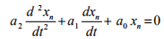
Let us consider a linear time invariant circuit having several energy source elements is described by the following dynamic equation.
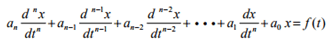
where a1, a2, a3, ••• an-1 , an are constant coefficients associated in the differential equation and they are dependent on circuit parameters (like, R, L and C for electric circuit) but independent of time, f (t) is the forcing or driving function and x(t) is the solution of differential equation or response of the system. We shall discussion the solution of differential equation restricted to second order differential, say n = 2 in equation (10.A1).
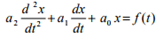
The solution of this differential equation provides the response of circuit and it is given by
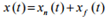
where xn(t) is the natural response of circuit, obtained by setting f (t) = 0, and xf (t) is the forced response that satisfies the original differential equation (10.A2).
By setting f (t) = 0 in equation (10.A2), as given in equation (10.A4), the force free equation is obtained
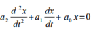 (Homogeneous equation)
The solution of such differential equation (or homogeneous equation) is known as natural solution or complementary solution or transient solution and it is denoted by xn (t). To get the natural solution xn (t) of equation (10.A4) the following steps are considered.
Let us use the following operators
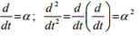
in equation (10.A4) and results an equation given by
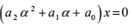
Since x ≠ 0 , the above equation can be written as
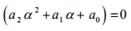
which is known as characteristic equation for a circuit whose force free equation is Eq.(10.A4). The natural or transient solution of Eq.(10.A4) is expressed by the exponential terms as given below.
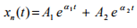
where α1 and α2 are the roots of characteristic equation (10.A5). The roots of second order characteristic equation with real coefficients is either real or complex occur in conjugate pairs. The constants A1 and A2 are evaluated from initial or boundary conditions of circuit. The principles of continuity of inductance current and capacitance voltage are used to establish the required boundary conditions.
If xn (t) is the natural or transient solution of unforced (or homogeneous) equation differential, it must satisfy its own differential equation
Further, if 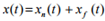 is the complete solution of given differential Eq.(10.A2), it must satisfy its own equation
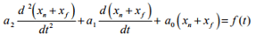
Using the equation (10.A7) in Eq.(10.A8), we get
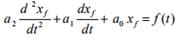
The above equation implies that xf (t) is the forced solution or steady state solution of second order differential equation (10.A2). Steady state solution of some common forcing functions is listed in Table (assume 
Table: Steady state solution xf (t) for any order differential equation excited by some common forcing function.
Type of forcing function f (t) (input) | Steady state solution xf (t) (output) |
|
|
|
|
|
|
|
|
|
|
|
|
|
|
|
|
Coefficients involve in the steady state solution can be found out by using the boundary conditions of the circuit.
Remark-7
(i) Eq. (10.A2) is the differential equation description of a linear circuit, superposition may be used to find the complete solution of a forcing function which is sum of natural and steady state responses. (ii) Eq.(10.A6) is the natural solution of force-free linear differential equation. Note that the constants α1 and α2 are the roots of the characteristic equation (10.A5) and they are entirely depending on the circuit parameters. The roots of the characteristic equation may be classified as
Case-1: Real or Complex but distinct
The natural solution of homogeneous equation (10.A4) is given as
Case-2: Roots are repeated (i.e. α1 = α2 = α or multiplicity of roots of order 2) The natural solution of homogeneous equation (10.A4) is given as
FAQs on Study of DC Transients in R-L & R-C Circuits - 3 - Electrical Engineering (EE)
| 1. What is a DC transient in an R-L circuit? |  |
| 2. How does an R-C circuit respond to a DC transient? | |
| 3. What is the time constant of an R-L circuit? | |
| 4. How does the time constant affect the transient response in an R-C circuit? | |
| 5. What is the difference between a transient response and a steady-state response in an R-L or R-C circuit? | |


video lectures
,mock tests for examination
,Exam
,Viva Questions
,Objective type Questions
,Study of DC Transients in R-L & R-C Circuits - 3 - Electrical Engineering (EE)
,Important questions
,Free
,study material
,Sample Paper
,Summary
,Study of DC Transients in R-L & R-C Circuits - 3 - Electrical Engineering (EE)
,Semester Notes
,Extra Questions
,practice quizzes
,Previous Year Questions with Solutions
,Study of DC Transients in R-L & R-C Circuits - 3 - Electrical Engineering (EE)
,past year papers
,MCQs
,ppt
,shortcuts and tricks
;


Study of DC Transients in R-L & R-C Circuits - 3 Free PDF Download
Importance of Study of DC Transients in R-L & R-C Circuits - 3
Study of DC Transients in R-L & R-C Circuits - 3 Notes
Study of DC Transients in R-L & R-C Circuits - 3 Electrical Engineering (EE) Questions
Study Study of DC Transients in R-L & R-C Circuits - 3 on the App
|
© EduRev
|
Education Revolution
|


|


