Properties of Concrete and Steel


Instructional Objectives:
At the end of this lesson, the student should be able to:
- know the properties of concrete in respect of strength, deformation and durability
- know the properties of steel used as reinforcement in concrete structures
- understand the importance of quality control, inspection and testing of concrete and steel in several steps from its basic preparation to the removal of formwork after the construction
- recommend the acceptance of good concrete based on sample test of specimens, core tests, load test and non-destructive tests
Introduction
It is essential that the designer acquires a sound knowledge of the materials used for reinforced concrete design. This lesson summarises the characteristic properties of concrete and steel, the two basic materials used for reinforced concrete. The summary provides the minimum information needed for design and inspection of reinforced concrete structures.
Properties of Concrete
Plain concrete is produced by mixing cement, sand (fine aggregate), coarse aggregate (gravel or crushed stone), and water in specific proportions. Mineral admixtures may be added to enhance particular properties. The strength and deformation behaviour of concrete therefore depend on the properties of its constituent materials, the mix proportions, and the processes of mixing, placing, compaction and curing. The Indian Standard IS 456:2000 (clauses 5 and 6) gives requirements for individual materials and concrete.
Plain concrete is strong in compression and weak in tension. To resist tensile stresses, steel reinforcement is embedded at appropriate locations to form reinforced concrete. The rate of strength gain of normal Portland cement concrete is rapid during early days and becomes marginal after 28 days; some blended cements (for example, those containing fly ash) gain strength more slowly, as recognised by codes.
(a) Characteristic strength property
Characteristic strength is defined as the strength below which not more than 5% of test results are expected to fall. Concrete is graded on the basis of the characteristic compressive strength of a specified specimen at 28 days and is expressed in N/mm². Grades are designated by the letter M (for mix) followed by a number equal to the characteristic compressive strength in N/mm². As per IS 456 (Table 2), concrete is grouped as:
- ordinary concrete: M10 to M20
- standard concrete: M25 to M55
- high strength concrete: M60 to M80
Note: specimen size for determining characteristic strength may vary between countries; in the Indian practice the 150 mm cube at 28 days is standard.
(b) Other strengths of concrete
Concrete also possesses flexural and splitting tensile strengths. These are determined by standard tests given in IS 516 (flexural) and IS 5816 (splitting tensile). A commonly used estimate for flexural strength fcr from characteristic cube compressive strength fck is given below (see clause 6.2.2 of IS 456):
fcr = 0.7

in N/mm2 (1.1)
(c) Elastic deformation of concrete
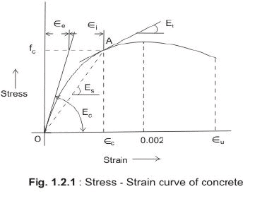
Figure 1.2.1 illustrates a typical compressive stress-strain curve for concrete.
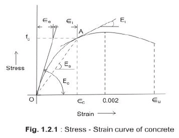
On the curve the following are defined:
- Ec = initial tangent modulus at the origin (short-term static modulus)
- Es = secant modulus at a point A on the curve
- Et = tangent modulus at point A
- εe = elastic strain at A
- εi = inelastic strain at A
The initial tangent modulus Ec is higher than Et. Near failure the total strain has elastic and inelastic components. The initial tangent modulus Ec, in N/mm², may be estimated from the code expression (clause 6.2.3):
Ec =
(1.2)
where fck is the characteristic compressive strength of concrete at 28 days. Ec is used to calculate short-term elastic deflections of reinforced concrete members.
(d) Shrinkage of concrete
Shrinkage is a time-dependent deformation (generally contraction) resulting primarily from loss of water and internal chemical changes in the cement paste. Total shrinkage depends on cement content, water content at mixing, aggregate properties, member size (surface-to-volume ratio), and environmental humidity and temperature. For design, in the absence of measured data, the approximate total shrinkage strain may be taken as 0.0003 (Clause 6.2.4.1 of IS 456:2000).
(e) Creep of concrete
Creep is additional time-dependent deformation under sustained load. Part of the deformation recovers when the load is removed. Figure 1.2.2 illustrates elastic recovery and slower creep recovery after unloading.
Short-term strain at load fc is
εc = fc / Ec (1.3)
Ultimate creep strain is εcr and the creep coefficient θ is defined by (clause 6.2.5.1):
θ = εcr / εc =

(1.4)
Typical values of θ at different ages of loading are: θ = 2.2 at 7 days, θ = 1.6 at 28 days and θ = 1.1 at 365 days (these give an indication of decreasing creep coefficient with later loading ages).
Total strain = εc + εcr (1.5)
Defining the effective (long-term) modulus Ece so that fc = Ece (εc + εcr), from (1.3)-(1.5) the relation becomes:
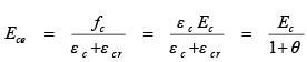
(1.6)
The effective modulus Ece is used for calculating long-term deflections due to sustained loads. Factors influencing creep include:
- properties of concrete (constituents and their proportions)
- water/cement ratio
- humidity and temperature during curing and service
- age of concrete at first loading
- magnitude and duration of applied stress
- surface-to-volume ratio of the member
(f) Thermal expansion of concrete
The coefficient of thermal expansion is required when temperature changes cause restraint or free expansion/contraction. It depends on aggregate type, cement type and content, humidity and section size. IS 456 (clause 6.2.6) provides values of coefficient of thermal expansion (per °C) for different aggregate types and concretes. Thermal effects are also important during fire exposure.
Workability and Durability of Concrete
Workability and durability affect constructability and service life. These are summarised below.
(a) Concrete mix proportioning
Mix proportions of cement, fine and coarse aggregates, water and admixtures must ensure:
- sufficient workability for placing and compaction
- required strength and durability after hardening
- acceptable surface finish
In modern practice a significant proportion of concrete includes admixtures to improve workability, setting, or durability.
(b) Workability
Workability is the ease and homogeneity with which fresh concrete can be mixed, placed, compacted and finished. A workable concrete should not segregate or bleed excessively. Segregation produces voids and lower durability; bleeding produces surface pores and can reduce durability. Workability is commonly measured by the slump test; IS 456 (clause 7) classifies degrees of workability from very low to very high with corresponding slump ranges.
(c) Durability
Durability is the ability of concrete to perform satisfactorily in its intended environment throughout its service life. Durable concrete has low permeability, adequate cement content, low free water/cement ratio and is fully compacted and properly cured. For full guidance refer to clause 8 of IS 456.
(d) Design mix and nominal mix concrete
In design mix (or proportioned mix) the quantities of materials are calculated to meet target mean strength, workability and durability requirements. In a nominal mix, fixed proportions are adopted without detailed proportioning. Design mix is preferred where specified strength and workability are required (IS 456, clause 9).
(e) Batching
Two common batching methods are mass (weight) and volume. Quantities of cement, fine and coarse aggregates and solid admixtures shall be measured by mass. Liquid admixtures and water may be measured by mass or by volume (IS 456, clause 10).
Properties of Steel
Steel reinforcement provides tensile resistance and ductility in reinforced concrete. Reinforcing bars are manufactured in specific nominal diameters. Bars up to 12 mm diameter are generally coiled for transport and termed bars, while bars over 12 mm are usually supplied in straight lengths and termed rods. Reinforcement types and standards (IS 456, clause 5.6) include:
- mild steel and medium tensile bars conforming to IS 432 (Part 1)
- high yield strength deformed (HYSD) bars conforming to IS 1786
- hard-drawn steel wire fabric conforming to IS 1566
- structural steel conforming to Grade A of IS 2062
Over time mild steel bars were largely replaced by HYSD and subsequently by TMT bars in practice. The designer must consider implications of different cement blends and steel types before adoption.
Stress-strain curves for reinforcement
Representative stress-strain behaviour for two classes of steel are shown in Figures 1.2.3 and 1.2.4.
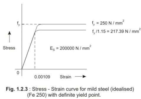
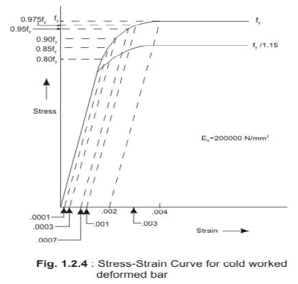
The characteristic yield strength fy is taken as the minimum yield stress, or where there is no definite yield point, as the 0.2% proof stress. The modulus of elasticity of steel Es is taken as 200 000 N/mm².
For mild steel (with distinct yield point) the stress is proportional to strain up to the yield. After yield the strain increases rapidly while the stress is generally assumed constant near fy for simplified design (Figure 1.2.3).
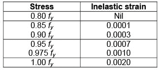
For cold-worked or high-strength deformed bars (without a distinct yield plateau), the elastic proportionality holds up to about 0.8 fy, beyond which the stress-strain inelastic curve is defined approximately by a specified relation.
Two common grades of cold-worked bars are Fe 415 and Fe 500, with fy = 415 N/mm² and 500 N/mm² respectively.
Using a material safety factor γm for steel (commonly taken as 1.15), the design yield stress fyd is computed as:
fyd = fy / γm (1.7)
Representative design stress-strain curves are obtained by substituting fyd for fy in the representative diagrams.
Other Important Factors (Practical Site Requirements)
To obtain the desired strength and durability the following site practices and checks are important; references to relevant clauses of IS 456 are noted.
(a) Mixing (clause 10.3)
Concrete shall be mixed in a mechanical mixer for sufficient time (typically at least two minutes after all materials are added) until uniform colour and consistency are achieved for uniform distribution of constituents.
(b) Formwork (clause 11)
Formwork must be rigid and watertight to prevent loss of slurry and to maintain the designed shape and surface finish. Striking (removal) of formwork should follow the minimum periods given in IS 456 so that the concrete achieves sufficient strength before removal. Formwork design should allow safe and efficient striking without damage to the concrete or undue shock.
(c) Assembly of reinforcement (clause 12)
Reinforcement for bending, shear and axial loads should be laid as per the bar bending schedule and secured to maintain required cover and spacing. Bars should rest on adequate chairs or spacers. High-strength deformed bars should not be re-bent unnecessarily. Reinforcement shall be arranged to allow free flow of concrete during placing and vibration.
(d) Transporting, placing, compaction and curing (clause 13)
Concrete must be transported to the place of deposit promptly after mixing to avoid segregation, loss of ingredients or loss of workability. In hot weather prevent rapid evaporation; in cold weather prevent loss of heat. Concrete should be placed as near as possible to its final position to avoid re-handling.
Compaction using mechanical vibrators is essential, especially around reinforcement, embedded fixtures and corners, to avoid honeycombing. Excessive vibration causes segregation and must be avoided.
Curing prevents loss of moisture and ensures satisfactory hydration and strength gain. Moist curing by ponding or wet coverings (sacking, canvas, hessian) is commonly used for 7-14 days depending on cement type and weather; blended cements often require longer curing. Impermeable membranes (polyethylene sheets) may be used to reduce evaporation when appropriate.
(e) Sampling and strength of designed concrete mix (clause 15)
Random samples of fresh concrete shall be taken; cubes (150 mm) are cast, cured and tested at 28 days as per IS 516. Additional tests at 7 days or modulus of rupture tests on beams at 3 or 7 days may be carried out. The number of samples depends on the total quantity of concrete (see clause 15.2.2). Each sample should have three specimens for 28-day testing and additional specimens if early-age tests are required.
(f) Acceptance criteria (clause 16)
Concrete is satisfactory when both the mean strength of any group of four consecutive test results and any single individual test result of compressive or flexural strength meet the limits prescribed in IS 456 (clause 16).
(g) Inspection and testing of structures (clause 17)
Systematic inspection of materials, workmanship and construction records is essential. All materials and reinforcement should be tested to the relevant standards. Dimensional tolerances, detailing and constructability should be checked. After removal of formwork, inspect for defects and rectify before concrete hardens further.
When doubts arise regarding in-situ concrete strength, standard core tests (IS 516) should be carried out at representative points. Acceptance of cores is based on comparisons with laboratory cube strength; if the average equivalent cube strength of cores is at least 85% of the specified cube strength and each individual core is at least 75%, the concrete represented by those cores is acceptable. Unsatisfactory core results require load tests for flexural members and analytical investigations for non-flexural members.
Load test procedure for flexural members: test as soon as practicable after 28 days from casting; apply full dead load and 1.25 times the imposed load for 24 hours, then remove the imposed load. Maximum deflection under the imposed load in mm should be less than 40 l² / D, where l is effective span in metres and D is overall depth in mm. If deflection exceeds this limit, note recovery within 24 hours after removal of imposed load; if recovery is less than 75% repeat test after 72 hours. The structure is unacceptable if recovery is less than 80%.
Non-destructive tests (NDT) such as ultrasonic pulse velocity (UPV), rebound hammer, probe penetration, pull-out and maturity methods may be used to supplement or, in some agreed cases, to partially replace core testing. Acceptance criteria for NDT shall be agreed prior to testing. UPV tests shortly after removal of formwork (for example at three days) can provide early indication of concrete quality.
Concluding Remarks
Reinforced concrete combines the compressive strength and mouldability of concrete with the tensile strength and ductility of steel, enabling architects and engineers to realise a wide range of forms and structural systems. The final strength and durability of reinforced concrete depend on the constituent materials, their proportions, proper mixing, placing, compaction and curing, and on adequate protection of reinforcement.
Concrete cover to reinforcement provides the oxygen- and moisture-limited environment required to reduce corrosion of embedded steel. Both the depth and the quality of cover are important. Inspection, sample testing, core tests, load tests and non-destructive testing are essential elements of quality assurance. Small defects discovered early (for example on removal of formwork) should be repaired before concrete fully hardens.
The designer's responsibility includes selection of materials, specification of mix, detailing and ensuring that construction procedures and testing arrangements are capable of producing the intended structural and durability performance.
Practice Questions and Problems with Answers
Q.1: What are the constituent materials of plain concrete?
A.1: The constituent materials of plain concrete are cement, sand (fine aggregate), gravel (coarse aggregate), water and mineral admixtures in some special cases.
Q.2: Define characteristic strength fck of concrete.
A.2: Characteristic strength of concrete is defined as the compressive strength of 150 mm size cube at 28 days and expressed in N/mm2 below which not more than five per cent of the test results are expected to fall.
Q.3: How and when the characteristic compressive strength fck is determined?
A.3: Characteristic compressive strength is determined by conducting compressive strength tests on specified number of 150 mm concrete cubes at 28 days after casting. It is expressed in N/mm2.
Q.4: What do the symbols M and 20 mean for grade M 20 concrete?
A.4: The symbol M refers to mix and the number 20 indicates that the characteristic strength fck of grade M 20 is 20 N/mm2.
Q.5: Express the relation between flexural strength (fcr) and characteristic compression strength fck of concrete.
A.5: The generally accepted relation is: fcr = 0.7

where fcr and fck are in N/mm2.
Q.6: Draw stress-strain curve of concrete and show the following: (a) Initial tangent modulus Ec, (b) Secant modulus Es at any point A on the stress-strain curve, (c) Tangent modulus Et at A and (d) elastic and inelastic strain components of the total strain at A.
A.6: Please refer to Fig. 1.2.1
Q.7: Express the short term static modulus Ec in terms of the characteristic compressive strength fck of concrete.
A.7: The suggested expression is : Ec = 5000

where Ec and fck are in N/mm2.
Q.8: State the approximate value of total shrinkage strain of concrete to be taken for the design purpose and mention the relevant clause no. of IS code.
A.8: As per cl. 6.2.4.1 of IS 456:2000, the approximate value of total shrinkage strain of concrete is to be taken as 0.0003.
Q.9: Define creep coefficient θ of concrete and express the relation between the effective modulus Ece, short term static modulus Ec and creep coefficient θ of concrete.
A.9: Creep coefficient θ is the ratio of ultimate creep strain εcr and short term strain at the age of loading (θ = εcr/εc). The required relation is Ece =

{The derivation of Eq. 1.6 is given in sec. 1.2.2 part (e)}.
Q.10: Define workability of concrete.
A.10: Workability of concrete is the property which determines the ease and homogeneity with which concrete can be mixed, placed, compacted and finished.
Q.11: Differentiate between design mix and nominal mix concrete.
A.11: In design mix, the proportions of cement, aggregates (sand and gravel), water and mineral admixtures, if any are actually determined by actual design to have a desired strength. In nominal mix, however, these proportions are nominally adopted.
Q.12: What are the different types of batching in mixing the constituent materials of concrete and name the type of batching to be adopted for different materials?
A.12: Mass and volume are the two types of batching. The quantities of cement, aggregates (sand and gravel) and solid admixtures shall be measured by mass batching. Liquid admixtures and water are measured either by mass or volume batching.
Q.13: Differentiate between steel bars and rods.
A.13: Bars are steel bars of diameter up to 12 mm which are coiled during transportation. Rods are steel bars of diameter greater than 12 mm and cannot be coiled. They are transported in standard lengths.
Q.14: Name the types of steel and their relevant IS standards to be used as reinforcement in concrete.
A.14: Please refer to sec. 1.2.4(i), (ii), (iii) and (iv).
Q.15: Draw stress-strain curve of steel bars with or without definite yield point and indicate the yield stress fy of them.
A.15: Please refer to Figs. 1.2.3 and 1.2.4. For steel bars of Fig. 1.2.3, fy = 250 N/mm2 and for steel bars of Fig. 1.2.4, fy = 415 and 500 N/mm2 for the two different grades.
Q.16: What are the criteria of properly mixed concrete and how to achieve them?
A.16: Properly mixed concrete will have uniform distribution of materials having uniform colour and consistency. These are achieved by mixing the constituent materials in a mechanical mixer at least for two minutes or such time till those qualities are achieved.
Q.17: What should be the expected strength of concrete structure at the time of removal of formwork?
A.17: The concrete at the time of removing the formwork should have strength of at least twice the stress that it may be subjected to at the time of removal of formwork.
Q.18: Name the sample tests to be performed for checking the strength of concrete.
A.18: The main test to be performed is 150 mm cube strength at 28 days made of fresh concrete and cured. Additional tests should also be conducted on 150 mm cubes at 7 days and beam tests to determine modulus of rupture at 3 or 7 days. There should be at least 3 or more samples of such specimens to represent the entire concrete work. Each sample should have at least three specimens for conducting each of the above-mentioned tests.
Q.19: Mention the specific acceptance criteria of the sample tests of cubes and beams.
A.19: Concrete should be considered satisfactory when both the mean strength determined from any group of four consecutive test results and any individual test result of compressive and flexural strength tests comply the prescribed limits of cl. 16 of IS 456.
Q.20: When is it essential to conduct standard core test?
A.20: Standard core tests are needed if the inspection of concrete work raises doubt regarding the grade of concrete either due to poor workmanship or unsatisfactory cube strength results performed following standard procedure.
Q.21: When do you consider core test results as satisfactory?
A.21: The core test results are considered satisfactory if:
- (i) the average equivalent cube strength of the cores is at least 85 per cent of the cube strength of the grade of concrete at that age, and
- (ii) each of the individual cores has strength of at least 75 per cent of the concrete cube strength at that age.
Q.22: What are to be done for unsatisfactory core test results?
A.22: Load tests are to be conducted for the flexural members and analytical investigations are to be performed for non-flexural members.
Q.23: Prescribe the loading conditions and age of structure for conducting load tests.
A.23: Load tests are to be conducted as soon as possible after expiry of 28 days from the date of casting. The flexural member is subjected to full dead load and 1.25 times the imposed load for 24 hours and then the imposed load has to be removed.
Q.24: When do you conclude the load tests as satisfactory?
A.24: Load tests are considered satisfactory if the maximum deflection in mm of the member during 24 hours under load is less than 40 l2/D, where l = effective span in m and D = overall depth of the member in mm. For members showing more deflection, the recovery of the deflection within 24 hours of removal of the imposed load has to be noted. If the recovery is less than 75 per cent of the deflection under imposed load, the tests should be repeated after a lapse of 72 hours. The structure is considered unacceptable if the recovery is less than 80 per cent.
Q.25: Name the acceptable non-destructive tests to be performed on structures.
A.25: The acceptable non-destructive tests are ultrasonic pulse velocity, rebound hammer, probe penetration, pull out and maturity.
Summary of this Lesson
Properties of concrete and steel in respect of strength, deformation and durability are essential for designers and site engineers. Quality control, inspection and testing from material selection through to removal of formwork are critical for achieving the intended performance. Indian Standards (IS 456:2000 and related codes) give guidance on grading, testing, acceptance criteria, and site practices. Proper mixing, placement, compaction, curing, and protection of reinforcement together ensure durable and safe reinforced concrete structures.
FAQs on Properties of Concrete and Steel
| 1. What's the difference between compressive strength and tensile strength in concrete? |  |
| 2. Why does concrete need steel reinforcement if it's already strong? | |
| 3. How does concrete's modulus of elasticity affect RCC design? | |
| 4. What causes concrete to lose strength over time, and how do durability properties help? | |
| 5. Why is the yield strength of steel more important than its ultimate tensile strength in concrete design? | |


