Traction vectors and stress tensors
Here we focus attention on a deformable continuum body B occupying an arbitrary region Bt of the Euclidean vector space with boundary surface ∂Bt at time t, as shown in figure 4.1a. We consider a general case where in arbitrary forces act on parts or the whole of the boundary surface called the external forces or loads. Recognizing that these external forces arose because we isolated the body from its surroundings, to find the internal forces we have to section the body. Thus, to find the internal forces on a internal surface passing through O, as indicated in the figure 4.1a, we have to section the body as shown in the figure 4.1b, with the cutting plane coinciding with the
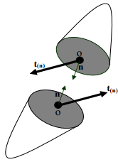
Figure 4.2: Traction vectors acting on infinitesimal surface elements with outward unit normal, n internal surface. Now, we focus our attention on an infinitesimal part of the body centered around O, see figure 4.2. Let x be the position vector of the point O, n a unit vector directed along the outward normal to an infinitesimal spatial surface element ∆s, at x and ∆f denote the infinitesimal resultant force acting on the surface element ∆s. Then, we claim that
 (4.1)
(4.1)
where t(n) =  represents the Cauchy (or true) traction vector and the integration here denotes an area integral. Thus, Cauchy traction vector is the force per unit surface area defined in the current configuration acting at a given location. The Cauchy traction vector and hence the infinitesimal force at a given location depends also on the orientation of the cutting plane, i.e., the unit normal n. This means that the traction and hence the infinitesimal force at the point O, for a vertical cutting plane could be different from that of a horizontal cutting plane. However, the traction on the two pieces of the cut body would be such that they are equal in magnitude but opposite in direction, in order to satisfy Newton’s third law of motion. Hence,
t(n) = −t(−n) . (4.2)
This requires: 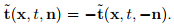
Relationship (4.1) is referred to as Cauchy’s postulate. It is worthwhile to mention that in any experiment we infer only these traction vectors. In literature, the traction vector is also called as stress vector because they have the units of stress, i.e., force per unit area. However, here we shall not use this terminology and for us stress is always a tensor, as defined next.
Cauchy stress theorem
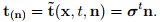
There exist unique second order tensor field σ, called the Cauchy (or true) stress tensor, so that
 (4.3)
(4.3)
where  is the position vector of the material particle in the reference configuration. It is easy to verify that the requirement (4.2) is met by (4.3). It will be shown in the next chapter that the Cauchy stress tensor, σ has to be a symmetric tensor. However, the proof of Cauchy stress theorem is beyond the scope of these lecture notes.
Components of Cauchy stress
It is recalled that only traction vector can be determined or inferred in the experiments and hence the components of the stress tensor is estimated from finding the traction vector on three (mutually perpendicular) planes. Let us see how. The components of the Cauchy stress tensor, σ with respect to an orthonormal basis {ea} is given by:
σab = ea · σeb = σtea · eb = t(ea) · eb, (4.4)
In view of Cauchy’s theorem t(ea) = σtea, a = 1, 2, 3, characterize the three traction vectors acting on the surface elements whose outward normals point in the directions e1, e2, e3, respectively. Then, the components of these traction vectors along e1, e2, e3 gives the various components of the stress tensor. Thus, for each stress component σab we adopt the mathematically logical convention that the index b characterizes the component of the traction vector, t(ea) , at a point x in the direction of the associated base vector eb and the index a characterizes the orientation of the area element on which t(n) is acting.

Figure 4.3: Cartesian components of the stress tensor acting on the faces of a cube
It is important to note that some authors reverse this convention by identifying the index b with the orientation of the normal to the plane of cut and the index a with the component of the traction along the direction ea. Irrespective of the convention adopted the end results will be the same because of two reasons: (i) The definition of divergence is suitably modified with a transpose (ii) the Cauchy stress tensor is anyway symmetric. In other words, to find the components of the Cauchy stress tensor, at a given location, we isolate an infinitesimal cube with the location of interest at its center. The cube is oriented such that the outward normal to its sides is along or opposite to the direction of the basis vectors. Hence, for general curvilinear coordinates, the sides of the cube need not be plane nor make right angles with each other. Compare the stress cube for Cartesian basis (figure 4.3) and cylindrical polar basis (figure 4.4). Then, we determine the traction that is acting on each of the six faces of the cube. Due to equation (4.2) only three of these six traction vectors are independent. The components of the three traction vectors along the the three basis vectors gives the nine components of the stress tensor.
If the component of the traction is along the direction of the basis vectors on planes whose outward normal coincides with the direction of the basis
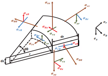
Figure 4.4: Cylindrical polar basis components of the stress tensor acting on the faces of a cube
vectors it is considered to be positive and negative otherwise. Consistently, if the component of the traction is opposite to the direction of the basis vectors on faces of the cube whose outward normal is opposite in direction to the basis vectors, it is considered to be positive and negative otherwise. Thus, one should not be confused that the same stress component points in opposite directions on opposite planes. This is necessary for the cube under consideration to be in equilibrium. It should also be appreciated that the sign of some of the stress component does change when the direction of the coordinate basis is reversed even if the right handedness of the basis vectors is maintained. This is so, because the sign of the stress component depends both on the direction of coordinate basis as well as the outward normal. Thus, figure 4.3 portrays the positive components of the stress tensor when Cartesian coordinate basis is used and it is called as the stress cube.
The positive cylindrical polar components of the stress tensor is depicted on a cylindrical wedge in figure 4.4. Recognize that the direction of the cylindrical polar components of the stress changes with the location unlike the Cartesian coordinate components whose directions are fixed. This happens because the direction of the cylindrical polar coordinate basis vectors depends on the location. Here σrr component of the stress is called as the radial stress,σθθ component of the stress is known as the hoop or the circumferential stress, σzz component of the stress is the axial stress.


