Asymmetrical Bending - Civil Engineering (CE) PDF Download

Asymmetrical bending
Having shown that for the symmetrical bending the strength of material approximation is robust when l/c > 10, we proceed to use the same approximation for asymmetrical bending. In the case of asymmetrical bending the loading plane does not coincide with the plane of symmetry. As an illustration, consider the rectangular section, loaded as shown in the figure 8.13a. The applied load can be resolved along the symmetry plane, as shown in figure 8.13b. Thus, the beam bends in both the xy plane due to loading along y direction and the xz plane due to loading along the z direction. As per the strength of materials assumption that the plane section before deformation remain plane and that the sections normal to the neutral axis, remain normal after the deformation, the displacement field for this case is,

where ∆y(x) and ∆z(x) are yet to be determined functions of x, yo and zo are constants. The above displacement field is obtained by superposing the bending displacement due to transverse loading along one symmetric plane, say xy plane, (8.29) and the displacement filed due to loading along another symmetric plane say xz (obtained by substituting z in place of y in equation (8.29)). Recollect from section 7.5.2 that for the linear elastic material that we are studying, we can superpose solutions as long as the displacements are small.
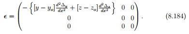
As required in the displacement approach, we next compute the linearized strain corresponding to the displacement field, (8.183) as
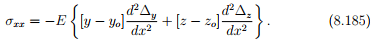
Then, using the 1 dimensional constitutive relation, the stress is obtained as
Substituting (8.185) in equation (8.3) and using the condition that no axial load is applied we obtain
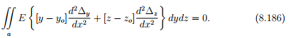
For equation (8.186) to hold we require that
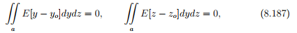
since in equation (8.186) ∆y and ∆z are independent functions of x and in particular ∆y ≠ −k∆z, where k is a constant. From equation (8.187) we obtain,
If the beam is also homogeneous then Young’s modulus, E is a constant and therefore,
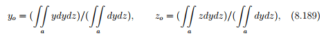
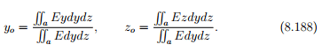
the y and z coordinates of the centroid of the cross section. Without loss of generality the origin of the coordinate system can be assumed to be located at the centroid of the cross section and hence yo = zo = 0. Since, we have assumed that there is no net applied axial load, i.e.,
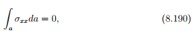
equation (8.9) and (8.8) can be written as,
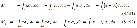
where yo and zo are constants as given in equation (8.188). Substituting equation (8.185) in equation (8.191) we obtain,
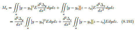
If the cross section of the beam is homogeneous, the above equation can be written as,
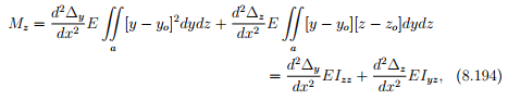
where
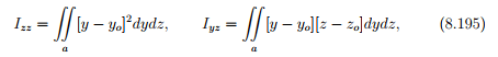
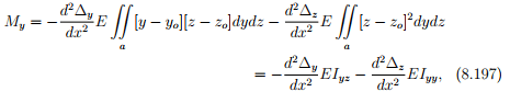
are the moment of inertia about the z axis, the axis about which the applied forces produces a moment, Mz and the product moment of inertia. Substituting equation (8.185) in equation (8.192) we obtain,
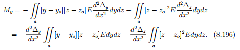
If the cross section of the beam is homogeneous, the above equation can be written as,
where
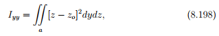
is the moment of inertia about the y axis, the axis about which the applied forces produces a moment, My. Solving equations (8.194) and (8.197) for ∆y and ∆z we obtain,
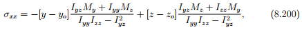
Substituting (8.199) in (8.185) we obtain
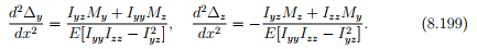
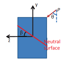
Figure 8.14: Schematic showing the neutral surface for a beam with rectangular cross section subjected to transverse loading
where yo and zo are as given in equation (8.189). Equation (8.200) gives the bending normal stress when a cross section is subjected to both My and Mz bending moments or when the cross section is subjected to a bending moment about an axis for which the product moment of inertia is not 0, i.e., loading is not along a plane of symmetry.
Before proceeding further, a few observations on equation (8.200) have to be made. It is clear from the equation (8.200) that the bending normal stress varies linearly over the cross sectional surface. As in the case of symmetrical bending, there exist a surface which has zero bending normal stress. This zero bending normal stress surface, called as the neutral surface is defined by
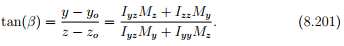
Figure 8.14 shows a typical neutral surface for a beam with rectangular cross section subjected to transverse loading not in the plane of symmetry of the cross section.
Having found the bending normal stress, next we find the bending shear stress. Towards this, we consider the equilibrium of a cuboid pqrstuvw as shown in figure 8.15, taken from a beam subjected to asymmetric bending moment that varies along the longitudinal axis of the beam. Note that on this cuboid, bending normal stress  acts on the face prtv and
  acts on the face qsuw, shear stress, σxy acts in plane rsvw and shear stress, σxz acts
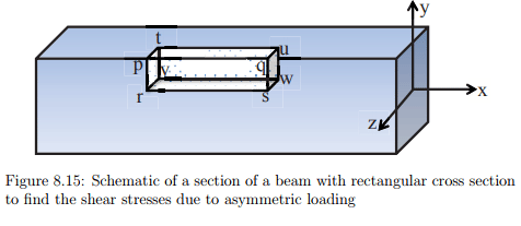
in plane tuvw. Now, the force balance along the x direction requires that

where we have assumed that constant shear stresses act on faces rsvw and pqrs and that the bending normal stress varies linearly over the faces prtv and qsuw as indicated in equation (8.200). Appealing to Taylor’s series, we write,
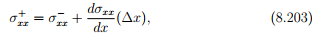
truncating the series after first order term, since our interest is in the limit (∆x) tending to zero. Differentiating (8.200) with respect to x we obtain,
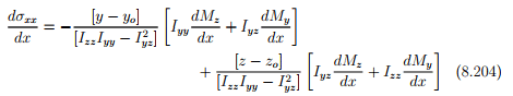
Substituting equations (8.18) and (8.20) in (8.204),
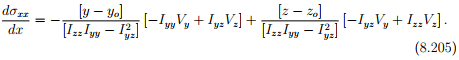
Substituting equation (8.205) in (8.203) and using the resulting equation in (8.202) we obtain
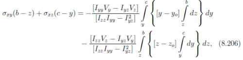
where the limits of the integration have been arrived at for the rectangular cross section shown in figure 8.15. Thus, if the section is thick walled, equation (8.206) is insufficient to determine all the shear stresses as such. Hence, strength of materials approach cannot yield the shear stresses in a thick walled section subjected to asymmetrical loading. However, it should be mentioned that the shear stresses in a well proportioned thick walled section, with l/c > 10, for which the strength of materials solution is applicable, will develop shear stresses which are an order of magnitude, at least, less than that of the bending stresses.
On the other hand since the direction of the shear stress is well defined in thin walled sections. It is going to be tangential to the cross section at the point of interest, as in the case of symmetric bending. Further, by virtue of the section being thin walled, we assume the shear stresses to be uniform across its thickness, t. Now, the shear stress, τ acting as shown in figure 8.16 balances the imbalance created due to the variation of the bending normal stresses along the longitudinal axis of the beam. Following the same steps as in the case of thick walled cross sections detailed above, it can be shown that
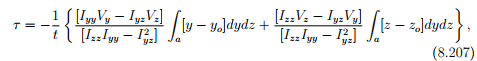
where the area over which the integration is to be performed is the shaded region shown in figure 8.16. If one is to use polar coordinates to describe the cross section and defining  the equation
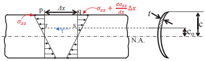
Figure 8.16: Stresses acting on a thin walled cross section beam subjected to asymmetric loading (8.207) can be written as,
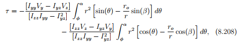
where r could be a function of θ but ro and β are constants. Thus, in equation (8.208) the shear stress, τ is a function of φ only. While this representation is convenient in cases where the section is not made up of straight line segments, a representation using the perimeter length, s, of the cross section is useful when the section is made up of straight line segments. Thus, the expression for the shear stress in terms of the perimeter length as shown in figure 8.16 is,
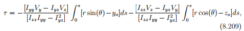
where now r and θ have to be expressed as a function of s. Here we have used the relation, ds = rdθ to obtain (8.209) from (8.208).
Thus, integrating the ordinary di erential equations (8.199) we obtain the de ections of the beam along the y and z directions and hence the displacement field for the beam, (8.183) can be computed. Using equation (8.200) the bending normal stress is evaluated. While these calculations are the same for thin or thick walled sections, the shear stress estimation is different. We could not nd the shear stresses in case of thick walled sections using the strength of materials approach. However, equation (8.207) gives the shear stresses in thin walled sections. This completes the solution to asymmetrical bending problem.
FAQs on Asymmetrical Bending - Civil Engineering (CE)
| 1. What is asymmetrical bending? |  |
| 2. What are some common causes of asymmetrical bending? | |
| 3. How does asymmetrical bending affect the structural integrity of an object? | |
| 4. What are some examples of asymmetrical bending in real-life applications? | |
| 5. How can asymmetrical bending be prevented or minimized? | |


Exam
,Previous Year Questions with Solutions
,study material
,Semester Notes
,Summary
,past year papers
,shortcuts and tricks
,practice quizzes
,Free
,Extra Questions
,MCQs
,Asymmetrical Bending - Civil Engineering (CE)
,Asymmetrical Bending - Civil Engineering (CE)
,Viva Questions
,Sample Paper
,mock tests for examination
,Important questions
,Objective type Questions
,video lectures
,ppt
,Asymmetrical Bending - Civil Engineering (CE)
;


Asymmetrical Bending Free PDF Download
Importance of Asymmetrical Bending
Asymmetrical Bending Notes
Asymmetrical Bending Civil Engineering (CE) Questions
Study Asymmetrical Bending on the App
|
© EduRev
|
Education Revolution
|


|


