Bond, Anchorage, Development Length and Splicing - Civil Engineering (CE) PDF Download

Instruction Objectives: At the end of this lesson, the student should be able to:
- understand the importance of bond and why is it essential to provide between steel and concrete,
- explain the development length,
- understand the need for anchoring the tensile bars,
- justify the superiority of deformed bars to smooth mild steel bars,
- define the design bond stress,
- understand the reason for different values of design bond stresses of plain bars and deformed bars in tension and compression,
- determine the development length of a single bar and bars bundled in contact,
- derive the expression to check the development length of bars in tension,
- specify the salient points of anchoring bars in tension, compression and shear,
- determine the bearing stress and check the same,
- take adequate precautions when the direction of reinforcement changes,
- specify the salient points of splicing and welding of reinforcement to make it longer,
- apply the theory for designing beams in different situations as may arise.
6.15.1 Introduction
The bond between steel and concrete is very important and essential so that they can act together without any slip in a loaded structure. With the perfect bond between them, the plane section of a beam remains plane even after bending. The length of a member required to develop the full bond is called the anchorage length. The bond is measured by bond stress. The local bond stress varies along a member with the variation of bending moment. The average value throughout its anchorage length is designated as the average bond stress. In our calculation, the average bond stress will be used. Thus, a tensile member has to be anchored properly by providing additional length on either side of the point of maximum tension, which is known as ‘Development length in tension’. Similarly, for compression members also, we have ‘Development length Ld in compression’. It is worth mentioning that the deformed bars are known to be superior to the smooth mild steel bars due to the presence of ribs. In such a case, it is needed to check for the sufficient development length Ld only rather than checking both for the local bond stress and development length as required for the smooth mild steel bars. Accordingly, IS 456, cl. 26.2 stipulates the requirements of proper anchorage of reinforcement in terms of development length Ld only employing design bond stress τbd.
6.15.2 Design Bond Stress τbd
(a) Definition
The design bond stress τbd is defined as the shear force per unit nominal surface area of reinforcing bar. The stress is acting on the interface between bars and surrounding concrete and along the direction parallel to the bars. This concept of design bond stress finally results in additional length of a bar of specified diameter to be provided beyond a given critical section. Though, the overall bond failure may be avoided by this provision of additional development length Ld, slippage of a bar may not always result in overall failure of a beam. It is, thus, desirable to provide end anchorages also to maintain the integrity of the structure and thereby, to enable it carrying the loads. Clause 26.2 of IS 456 stipulates, “The calculated tension or compression in any bar at any section shall be developed on each side of the section by an appropriate development length or end anchorage or by a combination thereof.”
(b) Design bond stress – values
Section 6.15.1 menti ons that the local bond stress varies along the length of the reinforcement while the average bond stress gives the average value throughout its development length. This average bond stress is still used in the working stress method and IS 456 has mentioned about it in cl. B-2.1.2. However, in the limit state method of design, the average bond stress has been designated as design bond stress τbd and the values are given in cl. 26.2.1.1. The same is given below as a ready reference.
Table 6.4 τbd for plain bars in tension
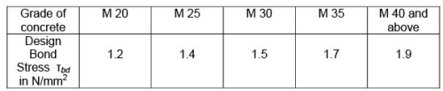
For deformed bars conforming to IS 1786, these values shall be increased by 60 per cent. For bars in compression, the values of bond stress in tension shall be increased by 25 per cent.
6.15.3 Development Length
(a) A single bar
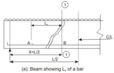
Figure 6.15.1(a) shows a simply supported beam subjected to uniformly distributed load. Because of the maximum moment, the Ast required is the maximum at x = L/2. For any section 1-1 at a distance x < L/2, some of the tensile bars can be curtailed. Let us then assume that section 1-1 is the theoretical cut-off point of one bar. However, it is necessary to extend the bar for a length Ld as explained earlier. Let us derive the expression to determine Ld of this bar.
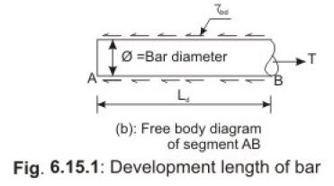
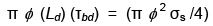
Figure 6.15.1(b) shows the free body diagram of the segment AB of the bar. At B, the tensile force T trying to pull out the bar is of the value T = (π φ 2 σs /4), where φ is the nominal diameter of the bar and σs is the tensile stress in bar at the section considered at design loads. It is necessary to have the resistance force to be developed by τbd for the length Ld to overcome the tensile force. The resistance force = π φ (Ld) (τbd). Equating the two, we get
 (6.11)
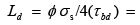
Equation 6.11, thus gives
 (6.12)
The above equation is given in cl. 26.2.1 of IS 456 to determine the development length of bars.
The example taken above considers round bar in tension. Similarly, other sections of the bar should have the required Ld as determined for such sections. For bars in compression, the development length is reduced by 25 per cent as the design bond stress in compression τbd is 25 per cent more than that in tension (see the last lines below Table 6.4). Following the same logic, the development length of deformed bars is reduced by 60 per cent of that needed for the plain round bars. Tables 64 to 66 of SP-16 present the development lengths of fully stressed plain and deformed bars (when σs = 0.87 fy) both under tension and compression. It is to be noted that the consequence of stress concentration at the lugs of deformed bars has not been taken into consideration.
(b) Bars bundled in contact
The respective development lengths of each of the bars for two, three or four bars in contact are determined following the same principle. However, cl. 26.2.1.2 of IS 456 stipulates a simpler approach to determine the development length directly under such cases and the same is given below:
“The development length of each bar of bundled bars shall be that for the individual bar, increased by 10 per cent for two bars in contact, 20 per cent for three bars in contact and 33 per cent for four bars in contact.” However, while using bundled bars the provision of cl. 26.1.1 of IS 456 must be satisfied. According to this clause:
- In addition to single bar, bars may be arranged in pairs in contact or in groups of three or four bars bundled in contact.
- Bundled bars shall be enclosed within stirrups or ties to ensure the bars remaining together.
- Bars larger than 32 mm diameter shall not be bundled, except in columns.
Curtailment of bundled bars should be done by terminating at different points spaced apart by not less than 40 times the bar diameter except for bundles stopping at support (cl. 26.2.3.5 of IS 456).
6.15.4 Checking of Development Lengths of Bars in Tension
The following are the stipulation of cl. 26.2.3.3 of IS 456.
(i) At least one-third of the positive moment reinforcement in simple members and one-fourth of the positive moment reinforcement in continuous members shall be extended along the same face of the member into the support, to a length equal to Ld/3.
(ii) Such reinforcements of (i) above shall also be anchored to develop its design stress in tension at the face of the support, when such member is part of the primary lateral load resisting system.
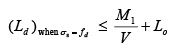
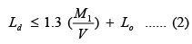
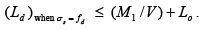
(iii) The diameter of the positive moment reinforcement shall be limited to a diameter such that the Ld computed for σs = fd in Eq. 6.12 does not exceed the following:
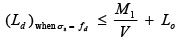 (6.13)
where M1 = moment of resistance of the section assuming all reinforcement at the section to be stressed to fd,
fd = 0.87 fy,
V = shear force at the section due to design loads,
Lo = sum of the anchorage beyond the centre of the support and the equivalent anchorage value of any hook or mechanical anchorage at simple support. At a point of inflection, Lo is limited to the effective depth of the member or 12φ , whichever is greater, and
φ = diameter of bar.
It has been further stipulated that M1/V in the above expression may be increased by 30 per cent when the ends of the reinforcement are confined by a compressive reaction.
6.15.5 Derivation of the Limiting Ld (Eq. 6.13)
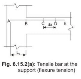
At the face of simple support and at the points of inflection in continuous beams, the tensile capacity to be developed is normally small although the rate of change of tensile stress in the bars is high. These bond stresses are designated as flexural bond stress.
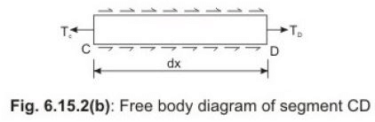
Figure 6.15.2(a) shows the tensile bar AB near the support of a beam and Fig. 6.15.2(b) explains the stresses and forces in the free body diagram of the segment CD of the bar. The tensile force at C (TC) is greater than that at D (TD). Considering z as the lever arm (distance between the centres of gravity of tensile and compressive force), we have MC = TC (z) (6.14)
MD = TD (z) Again TC - TD = πφ (dx) τ bd (6.15)
From Eqs.6.14 and 6.15,
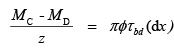
which gives
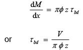 (6.16)
Equation 6.16 gives the flexural bond stress in the tension reinforcement at any section. If there are N bars of equal size, we have
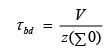 (6.17)
where ∑0 = N π φ = total perimeter of all bars in tension at the section. Again, for N bars of equal diameter, we get from Eq. 6.11:

which gives:
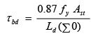 (6.18)
Equations 6.17 and 6.18 give:
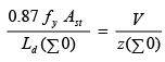
or  (6.19)
where M1 = 0.87 f y Ast z is the moment of resistance at the section and
V = shear force at the section
From Eq.6.19, we find that the ratio of M1/V at the section must be equal to or greater than Ld if the design bond stress τbd is to be restricted within limit. The stipulation of additional Lo in the expression of Eq.6.13 is for additional safety. The meaning of Lo has been mentioned in sec. 6.15.4 (iii).
6.15.6 Anchoring Reinforcing Bars
Section 6.15.2(a) mentions that the bars may be anchored in combination of providing development length to maintain the integrity of the structure. Such anchoring is discussed below under three sub-sections for bars in tension, compression and shear respectively, as stipulated in cl. 26.2.2 of IS 456.
(a) Bars in tension (cl. 26.2.2.1 of IS 456)
The salient points are:
- Derformed bars may not need end anchorages if the development length requirement is satisfied.
- Hooks should normally be provided for plain bars in tension.
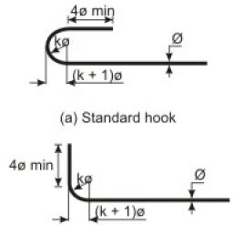
- Standard hooks and bends should be as per IS 2502 or as given in Table 67 of SP-16, which are shown in Figs.6.15.3 a and b.
- The anchorage value of standard bend shall be considered as 4 times the diameter of the bar for each 45o bend subject to a maximum value of 16 times the diameter of the bar.
- The anchorage value of standard U-type hook shall be 16 times the diameter of the bar.
(b) Bars in compression (cl. 26.2.2.2 of IS 456)
Here, the salient points are:
- The anchorage length of straight compression bars shall be equal to its development length as mentioned in sec. 6.15.3.
- The development length shall include the projected length of hooks, bends and straight lengths beyond bends, if provided.
(c) Bars in shear (cl. 26.2.2.4 of IS 456)

The salient points are:
- Inclined bars in tension zone will have the development length equal to that of bars in tension and this length shall be measured from the end of sloping or inclined portion of the bar.
- Inclined bars in compression zone will have the development length equal to that of bars in tension and this length shall be measured from the middepth of the beam.
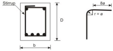
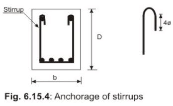
- For stirrups, transverse ties and other secondary reinforcement, complete development length and anchorage are considered to be satisfied if prepared as shown in Figs.6.15.4.
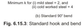
6.15.7 Bearing Stresses at Bends (cl. 26.2.2.5 of IS 456)
The bearing stress inside a bend is to be calculated from the expression:
Bearing stress =  (6.20)
where Fbt = tensile force due to design loads in a bar or group of bars,
r = internal radius of the bend, and
φ = size of the bar or bar of equivalent area in bundled bars.
The calculated bearing stress of Eq.6.20 shall not exceed the following:
Calculated bearing stress  (6.21)
where fck = characteristic cube strength of concrete
a = center to center distance between bars or groups of bars perpendicular to the plane of the bend. For bars adjacent to the face of the member, a shall be taken as cover plus size of the bar φ .
6.15.8 Change in Direction of Reinforcement (cl. 26.2.2.6 of IS 456)
In some situations, the change in direction of tension or compression reinforcement induces a resultant force. This force may have a tendency to split the concrete and, therefore, should be taken up by additional links or stirrups. Normally, this aspect is taken care while detailing of bars is carried out.
6.15.9 Reinforcement Splicing (cl. 26.2.5 of IS 456)
Reinforcement is needed to be joined to make it longer by overlapping sufficient length or by welding to develop its full design bond stress. They should be away from the sections of maximum stress and be staggered. IS 456 (cl. 26.2.5) recommends that splices in flexural members should not be at sections where the bending moment is more than 50 per cent of the moment of resistance and not more than half the bars shall be spliced at a section.
(a) Lap Splices (cl. 26.2.5.1 of IS 456)
The following are the salient points:
- They should be used for bar diameters up to 36 mm.
- They should be considered as staggered if the centre to centre distance of the splices is at least 1.3 times the lap length calculated as mentioned below.
- The lap length including anchorage value of hooks for bars in flexural tension shall be Ld or 30φ , whichever is greater. The same for direct tension shall be 2Ld or 30φ , whichever is greater.
- The lap length in compression shall be equal to Ld in compression but not less than 24φ .
- The lap length shall be calculated on the basis of diameter of the smaller bar when bars of two different diameters are to be spliced.
- Lap splices of bundled bars shall be made by splicing one bar at a time and all such individual splices within a bundle shall be staggered.
(b) Strength of Welds (cl. 26.2.5.2 of IS 456)
The strength of welded splices and mechanical connections shall be taken as 100 per cent of the design strength of joined bars for compression splices.
For tension splices, such strength of welded bars shall be taken as 80 per cent of the design strength of welded bars. However, it can go even up to 100 per cent if welding is strictly supervised and if at any cross-section of the member not more than 20 per cent of the tensile reinforcement is welded. For mechanical connection of tension splice, 100 per cent of design strength of mechanical connection shall be taken.
6.15.10 Numerical Problems
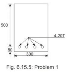
Problem 1:
Determine the anchorage length of 4-20T reinforcing bars going into the support of the simply supported beam shown in Fig. 6.15.5. The factored shear force Vu = 280 kN, width of the column support = 300 mm. Use M 20 concrete and Fe 415 steel.
Solution 1:
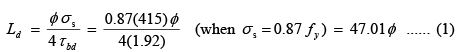
Table 6.4 gives τbd for M 20 and Fe 415 (with 60% increased) = 1.6(1.2) = 1.92 N/mm2 Eq.6.12 gives
Eq.6.13 gives
Here, to find M1, we need xu
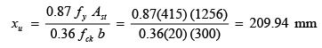
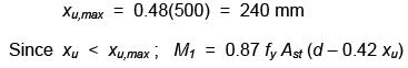
or M1 = 0.87(415) (1256) {500 – 0.42(209.94)} = 187.754 kNm
and V = 280 kN
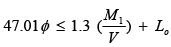
We have from Eq.6.13 above, with the stipulation of 30 per cent increase assuming that the reinforcing bars are confined by a compressive reaction:
From Eqs.(1) and (2), we have
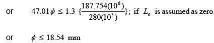
Therefore, 20 mm diameter bar does not allow Lo = 0.
Determination of Lo:
Minimum 
So, the bars are extended by 100 mm to satisfy the requirement as shown in Fig.6.15.6.
6.15.11 Practice Questions and Problems with Answers
Q.1: Explain the importance of the bond and why is it essential to provide between steel and concrete in beams?
A.1: Sec. 6.15.1 para 1
Q.2: Define the design bond stress τ bd .
A.2: Sec. 6.15.2(a)
Q.3: State the percentage increase/decrease of design bond stress of deformed bars in tension and compression with reference to the respective values of plain bars.
A.3: Three lines below Table 6.4 of sec. 6.15.2(b)
Q.4: Derive the expression of determining the development length of a single bar in tension. State the changes, if any, for the compression bars.
A.4: Sec. 6.15.3(a).
Q.5: How would you determine the development lengths of bars when two, three or four bars are bundled in contact? State the salient points of the stipulations of IS 456 in this respect.
A.5: Sec. 6.15.3(b)
Q.6: Derive the limiting value of the development length for bars in tension having both bending moment and shear force. Explain the role of additional length Lo. A.6: Sec. 6.15.5 and the final form is given in Eq.6.13.
Q.7: State the salient points of the stipulations of IS 456 regarding anchoring reinforcing bars in tension, compression and shear, respectively.
A.7: Sec. 6.15.6(a), (b) and (c) are the respective answers.
Q.8: Write down the expressions of calculated bearing stress at bends and its limiting value.
A.8: Eqs.6.20 and 6.21 are the answers.
Q.9: State the additional measure to be taken when the reinforcing bars change the direction.
A.9: Sec. 6.15.8.
Q.10: State the salient points of splicing and welding of reinforcing bars.
A.10: Sec. 6.15.9(a) and (b), respectively, are the answers.
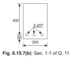
Q.11: Check the bond requirement of the continuous beam of Fig.6.15.7 if the factored shear force is 200 kN at the point of inflection. Assume M 20 and Fe 415.
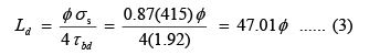
A.11: Table 6.4 gives τbd for M 20 and Fe 415 as 1.92 N/mm2 (see Solution 1 of Problem 1 of sec. 6.15.10). Eq.6.12 gives
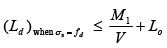
Eq.6.13 gives
To find M1, we need xu
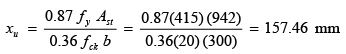
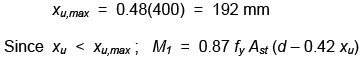
= 0.87(415) (942) {400 – 0.42(157.46)} = 113.55 kNm ….. (4)
From Eqs. (3) and (4), we have
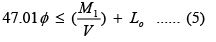
At the point of inflection Lo is the maximum of d (= 400 mm) or 12φ (= 240 mm).
With Lo = 400 mm, we can write from Eq.(5)
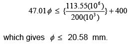
Thus, use of φ = 20 mm satisfies the bond requirement.
6.15.12 Test 15 with Solutions
Maximum Marks = 50,
Maximum Time = 30 minutes
Answer all questions.
TQ.4: Design the main tensile reinforcement of a singly reinforced rectangular beam of width 300 mm and effective span of 8 m carrying a total factored load of 40 kN/m using M 20 and Fe 415 with the help of SP-16. Check the development length at the support if 50 per cent of the reinforcing bars are continued to the support. Assume width of the support as 300 mm. (20 marks)
A.TQ.4: Design of beam using SP-16: Factored mid-span bending moment = 40(8)(8)/8 = 320 kNm Factored shear at the support = 40(8)/2 = 160 kN Required moment of resistance per metre width = 320/0.3 = 1067 kNm/m
Chart 15 of SP-16 gives d = 63.25 cm and percentage of reinforcement = 0.9.
Using the total depth D = 700 mm and effective depth as 650 mm, we get the area of main tensile reinforcement at mid-span = 0.9(bd)/100 = 0.9(300)(650)/100 = 1755 mm2.
Let us provide 6-20T of area = 1885 mm2.
Three 20T bars (50 per cent) are continued at the support.
The value of ζ bd for M 20 and Fe 415 is obtained from Table 6.4 with 60 per cent increased as 1.92 N/mm2.
Eq.6.12 gives
 (20)(0.87)(415)/4(1.92) = 940.23 mm (6)
 To find M1, we need xu as given below:
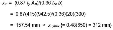
So,
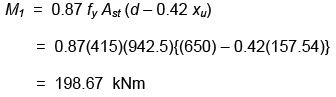
We have from Eq.6.13 with the stipulation of increase of 30 per cent assuming that the reinforcing bars are confined by a compressive reaction:
Ld ≤ 1.3(M1/V) + Lo
(7)
From Eqs.6 and 7 above, we have 940.23 ≤ 1.3 (M1/V) + Lo
(8)
Here, 1.3(M1/V) = 1.3(198.67)/160 = 1.614 m
Hence, Lo is not required as Ld is satisfied when Lo = 0 (sec. Eq.8). 6.15.14
Summary of this Lesson
This lesson explains the importance of bond between steel and concrete which is essential for the two materials to act together. To ensure the bond, additional length of the reinforcing bars is to be provided, which is known as the development length and calculated on the basis of design bond stresses. The design bond stress has been defined in this lesson and the values of the design bond stresses for different grades of concrete are given for mild steel plain and ribbed steel bars. The expression of determination of development length has been derived. The stipulations of IS 456 regarding anchoring bars in tension, compression and shear are discussed. Numerical problems solved in the lesson and other examples of practice problem and test question explain the calculations of satisfying the requirements of reinforcing bars under different situations with respect to bond.
FAQs on Bond, Anchorage, Development Length and Splicing - Civil Engineering (CE)
| 1. What is a bond in civil engineering? |  |
| 2. What is the significance of anchorage in civil engineering? | |
| 3. What is development length in civil engineering? | |
| 4. How is the development length calculated in civil engineering? | |
| 5. What is splicing in civil engineering? | |


Exam
,Development Length and Splicing - Civil Engineering (CE)
,Objective type Questions
,video lectures
,Semester Notes
,past year papers
,Sample Paper
,Anchorage
,Summary
,study material
,Bond
,shortcuts and tricks
,practice quizzes
,Extra Questions
,Anchorage
,Bond
,Free
,Anchorage
,Viva Questions
,MCQs
,Development Length and Splicing - Civil Engineering (CE)
,ppt
,Previous Year Questions with Solutions
,Bond
,Development Length and Splicing - Civil Engineering (CE)
,Important questions
,mock tests for examination
;


Bond, Anchorage, Development Length and Splicing Free PDF Download
Importance of Bond, Anchorage, Development Length and Splicing
Bond, Anchorage, Development Length and Splicing Notes
Bond, Anchorage, Development Length and Splicing Civil Engineering (CE) Questions
Study Bond, Anchorage, Development Length and Splicing on the App
|
© EduRev
|
Education Revolution
|


|


