Two way Slabs - Civil Engineering (CE) PDF Download

Two-way Slabs
Instructional Objectives: At the end of this lesson, the student should be able to:
- determine the shear force of two-way slabs subjected to uniformly distributed loads,
- state the two types of two-way slabs mentioning the differences between them,
- determine the preliminary depth of two-way slabs of different support conditions from the span to effective depth ratios as given in IS 456,
- explain the provisions of torsion reinforcing bars at two types of corners of a restrained two-way slab,
- design the two types of two-way slabs applying the different methods explained in this lesson and draw the detailing of reinforcing bars.
8.19.1 Introduction
the various types of slabs with different support conditions, plan forms, horizontal/inclined etc. Moreover, sec. 8.18.2 of Lesson 18 illustrates the sharing of uniformly distributed loads to the supporting beams of both one and two-way slabs including the profiles of deflection (Figs.8.18.4a and b). It is, thus, understood that two-way slabs span in both directions having the aspect ratio of ly/lx up to 2, considering lx as the shorter span. This lesson presents the different aspects of analysis and design of two-way slabs. Many of the stipulations of IS 456 are the same as those of one-way slabs. While mentioning the common stipulations with their respective section in Lesson 18, this lesson presents other relevant requirements regarding the analysis, design and detailing of two-way slabs. Numerical problems are also solved to illustrate the applications of the theory in the design of two-way slabs.
8.19.2 Two-way Slabs
Two-way slabs subjected mostly to uniformly distributed loads resist them primarily by bending about both the axis. However, as in the one-way slab, the depth of the two-way slabs should also be checked for the shear stresses to avoid any reinforcement for shear. Moreover, these slabs should have sufficient depth for the control deflection. Thus, strength and deflection are the requirements of design of two-way slabs.
8.19.3 Design Shear Strength of Concrete
Design shear strength of concrete in two-way slabs is to be determined incorporating the multiplying factor k from Table 8.1 of Lesson 18 in the same manner as discussed in sec. 8.18.3 of Lesson 18.
8.19.4 Structural Analysis
8.19.4.1 Computation of shear force
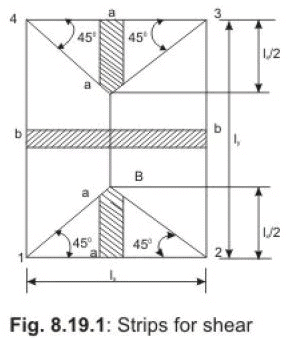
Shear forces are computed following the procedure stated below with reference to Fig.8.19.1. The two-way slab of Fig. 8.19.1 is divided into two trapezoidal and two triangular zones by drawing lines from each corner at an angle of 45o. The loads of triangular segment A will be transferred to beam 1-2 and the same of trapezoidal segment B will be beam 2-3. The shear forces per unit width of the strips aa and bb are highest at the ends of strips. Moreover, the length of half the strip bb is equal to the length of the strip aa. Thus, the shear forces in both strips are equal and we can write, Vu = W (lx/2) (8.1)
where W = intensity of the uniformly distributed loads. The nominal shear stress acting on the slab is then determined from
τ v = Vu / bd (8.2)
8.19.4.2 Computation of bending moments
Two-way slabs spanning in two directions at right angles and carrying uniformly distributed loads may be analysed using any acceptable theory. Pigeoud’s or Wester-guard’s theories are the suggested elastic methods and Johansen’s yield line theory is the most commonly used in the limit state of collapse method and suggested by IS 456 in the note of cl. 24.4. Alternatively, Annex D of IS 456 can be employed to determine the bending moments in the two directions for two types of slabs: (i) restrained slabs, and (ii) simply supported slabs. The two methods are explained below:
(i) Restrained slabs
Restrained slabs are those whose corners are prevented from lifting due to effects of torsional moments. These torsional moments, however, are not computed as the amounts of reinforcement are determined from the computed areas of steel due to positive bending moments depending upon the intensity of torsional moments of different corners. This aspect has been explained in Step 7 of sec. 8.19.6. Thus, it is essential to determine the positive and negative bending moments in the two directions of restrained slabs depending on the various types of panels and the aspect ratio ly/lx.
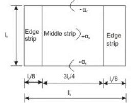
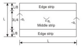
Restrained slabs are considered as divided into two types of strips in each direction: (i) one middle strip of width equal to three-quarters of the respective length of span in either directions, and (ii) two edge strips, each of width equal to one-eighth of the respective length of span in either directions. Figures 8.19.2a and b present the two types of strips for spans lx and ly separately.
The maximum positive and negative moments per unit width in a slab are determined from
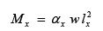 (8.3)
(8.3)
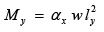 (8.4)
(8.4)
where αx and αy are coefficients given in Table 26 of IS 456, Annex D, cl. D1.1. Total design load per unit area is w and lengths of shorter and longer spans are represented by lx and ly, respectively. The values of αx and αy , given in Table 26 of IS 456, are for nine types of panels having eight aspect ratios of ly/lx from one to two at an interval of 0.1. The above maximum bending moments are applicable only to the middle strips and no redistribution shall be made. Tension reinforcing bars for the positive and negative maximum moments are to be provided in the respective middle strips in each direction. Figure 8.19.2 shows the positive and negative coefficients α x and αy . The edge strips will have reinforcing bars parallel to that edge following the minimum amount as stipulated in IS 456.
The detailing of all the reinforcing bars for the respective moments and for the minimum amounts as well as torsional requirements are discussed in sec. 8.19.7(i).
(ii) Simply supported slabs
The maximum moments per unit width of simply supported slabs, not having adequate provision to resist torsion at corners and to prevent the corners from lifting, are determined from Eqs.8.3 and 8.4, where αx and αy are the respective coefficients of moments as given in Table 27 of IS 456, cl. D-2. The notations Mx, My, w, lx and ly are the same as mentioned below Eqs.8.3 and 8.4 in (i) above. The detailing of reinforcing bars for the respective moments is explained in sec. 8.19.7(ii).
- The same ratios should be multiplied by 0.8 when high strength deformed bars (Fe 415) are used in the slabs.
- 8.19.6 Design of Two-way Slabs The procedure of the design of two-way slabs will have all the six steps mentioned in sec. 8.18.6 for the design of one-way slabs except that the bending moments and shear forces are determined by different methods for the two types of slab.
While the bending moments and shear forces are computed from the coefficients given in Tables 12 and 13 (cl. 22.5) of IS 456 for the one-way slabs, the same are obtained from Tables 26 or 27 for the bending moment in the two types of two-way slabs and the shear forces are computed from Eq.8.1 for the two-way slabs. Further, the restrained two-way slabs need adequate torsional reinforcing bars at the corners to prevent them from lifting. There are three types of corners having three different requirements. Accordingly, the determination of torsional reinforcement is discussed in Step 7, as all the other six steps are common for the one and two-way slabs.
Step 7: Determination of torsional reinforcement
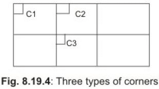
Three types of corners, C1, C2 and C3, shown in Fig.8.19.4, have three different requirements of torsion steel as mentioned below.
(a) At corner C1 where the slab is discontinuous on both sides, the torsion reinforcement shall consist of top and bottom bars each with layers of bar placed parallel to the sides of the slab and extending a minimum distance of onefifth of the shorter span from the edges. The amount of reinforcement in each of the four layers shall be 75 per cent of the area required for the maximum midspan moment in the slab. This provision is given in cl. D-1.8 of IS 456.
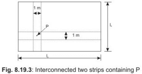
The coefficients αx and αy of simply supported two-way slabs are derived from the Grashoff-Rankine formula which is based on the consideration of the same deflection at any point P (Fig.8.19.3) of two perpendicular interconnected strips containing the common point P of the two-way slab subjected to uniformly distributed loads.
(b) At corner C2 contained by edges over one of which is continuous, the torsional reinforcement shall be half of the amount of (a) above. This provision is given in cl. D-1.9 of IS 456. (c) At corner C3 contained by edges over both of which the slab is continuous, torsional reinforcing bars need not be provided, as stipulated in cl. D1.10 of IS 456.
8.19.5 Design Considerations
The design considerations mentioned in sec. 8.18.5 of Lesson 18 in (a), (c), (d), (e) and (f) are applicable for the two-way slabs also. However, the effective span to effective depth ratio is different from those of one-way slabs. Accordingly, this item for the two-way slabs is explained below.
Effective span to effective depth ratio (cl. 24.1 of IS 456)
The following are the relevant provisions given in Notes 1 and 2 of cl. 24.1.
- The shorter of the two spans should be used to determine the span to effective depth ratio.
- For spans up to 3.5 m and with mild steel reinforcement, the span to overall depth ratios satisfying the limits of vertical deflection for loads up to 3 kN/m2 are as follows:
- Simply supported slabs 35
- Continuous slabs 40
- The same ratios should be multiplied by 0.8 when high strength deformed bars (Fe 415) are used in the slabs.
8.19.6 Design of Two-way Slabs
The procedure of the design of two-way slabs will have all the six steps mentioned in sec. 8.18.6 for the design of one-way slabs except that the bending moments and shear forces are determined by different methods for the two types of slab.
While the bending moments and shear forces are computed from the coefficients given in Tables 12 and 13 (cl. 22.5) of IS 456 for the one-way slabs, the same are obtained from Tables 26 or 27 for the bending moment in the two types of two-way slabs and the shear forces are computed from Eq.8.1 for the two-way slabs.
Further, the restrained two-way slabs need adequate torsional reinforcing bars at the corners to prevent them from lifting. There are three types of corners having three different requirements. Accordingly, the determination of torsional reinforcement is discussed in Step 7, as all the other six steps are common for the one and two-way slabs.
Step 7: Determination of torsional reinforcement
Three types of corners, C1, C2 and C3, shown in Fig.8.19.4, have three different requirements of torsion steel as mentioned below.
(a) At corner C1 where the slab is discontinuous on both sides, the torsion reinforcement shall consist of top and bottom bars each with layers of bar placed parallel to the sides of the slab and extending a minimum distance of onefifth of the shorter span from the edges. The amount of reinforcement in each of the four layers shall be 75 per cent of the area required for the maximum midspan moment in the slab. This provision is given in cl. D-1.8 of IS 456.
(b) At corner C2 contained by edges over one of which is continuous, the torsional reinforcement shall be half of the amount of (a) above. This provision is given in cl. D-1.9 of IS 456.
(c) At corner C3 contained by edges over both of which the slab is continuous, torsional reinforcing bars need not be provided, as stipulated in cl. D1.10 of IS 456.
8.19.7 Detailing of Reinforcement
As mentioned in sec. 8.19.6, Step 5 of sec. 8.18.6 explains the two methods of determining the required areas of steel required for the maximum positive and negative moments. The two methods are (i) employing Eq.3.23 as given in Step 5 of sec. 8.18.6 or (ii) using tables and charts of SP-16. Thereafter, Step 7 of sec. 8.19.6 explains the method of determining the areas steel for corners of restrained slab depending on the type of corner. The detailing of torsional reinforcing bars is explained in Step 7 of sec. 8.19.6. In the following, the detailings of reinforcing bars for (i) restrained slabs and (ii) simply supported slabs are discussed separately for the bars either for the maximum positive or negative bending moments or to satisfy the requirement of minimum amount of steel.
(i) Restrained slabs
The maximum positive and negative moments per unit width of the slab calculated by employing Eqs.8.3 and 8.4 as explained in sec. 8.19.4.2(i) are applicable only to the respective middle strips (Fig.8.19.2). There shall be no redistribution of these moments. The reinforcing bars so calculated from the maximum moments are to be placed satisfying the following stipulations of IS 456.
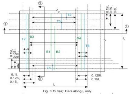
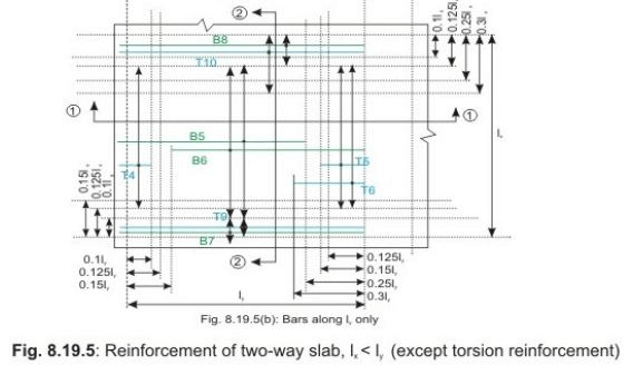

- Bottom tension reinforcement bars of mid-span in the middle strip shall extent in the lower part of the slab to within 0.25l of a continuous edge, or 0.15l of a discontinuous edge (cl. D-1.4 of IS 456). Bars marked as B1, B2, B5 and B6 in Figs.8.19.5 a and b are these bars.
- Top tension reinforcement bars over the continuous edges of middle strip shall extend in the upper part of the slab for a distance of 0.15l from the support, and at least fifty per cent of these bars shall extend a distance of 0.3l (cl. D-1.5 of IS 456). Bars marked as T2, T3, T5 and T6 in Figs.8.19.5 a and b are these bars.
- To resist the negative moment at a discontinuous edge depending on the degree of fixity at the edge of the slab, top tension reinforcement bars equal to fifty per cent of that provided at mid-span shall extend 0.1l into the span (cl. D-1.6 of IS 456). Bars marked as T1 and T4 in Figs.8.19.5 a and b are these bars.
The edge strip of each panel shall have reinforcing bars parallel to that edge satisfying the requirement of minimum amount as specified in sec. 8.18.15d of Lesson 18 (cl. 26.5.2.1 of IS 456) and the requirements for torsion, explained in
Step 7 of sec. 8.19.6 (cls. D-1.7 to D-1.10 of IS 456).
The bottom and top bars of the edge strips are explained below.
- Bottom bars B3 and B4 (Fig.8.19.5 a) are parallel to the edge along lx for the edge strip for span ly, satisfying the requirement of minimum amount of steel (cl. D-1.7 of IS 456).
- Bottom bars B7 and B8 (Fig.8.19.5 b) are parallel to the edge along ly for the edge strip for span lx, satisfying the requirement of minimum amount of steel (cl. D-1.7 of IS 456).
- Top bars T7 and T8 (Fig.8.19.5 a) are parallel to the edge along lx for the edge strip for span ly, satisfying the requirement of minimum amount of steel (cl. D-1.7 of IS 456).
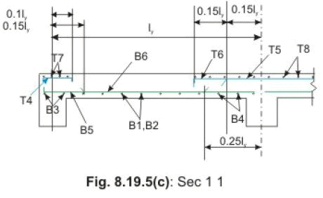
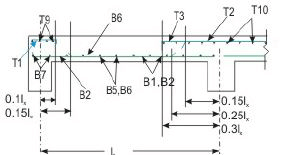
- Top bars T9 and T10 (Fig.8.19.5 b) are parallel to the edge along ly for the edge strip for span lx, satisfying the requirement of minimum amount of steel (cl. D-1.7 of IS 456). The detailing of torsion bars at corners C1 and C2 is explained in Fig.8.19.7 of Problem 8.2 in sec. 8.19.8. The above explanation reveals that there are eighteen bars altogether comprising eight bottom bars (B1 to B8) and ten top bars (T1 to T10). Tables 8.4 and 8.5 present them separately for the bottom and top bars, respectively, mentioning the respective zone of their placement (MS/LDES/ACES/BDES to designate Middle Strip/Left Discontinuous Edge Strip/Adjacent Continuous Edge Strip/Bottom Discontinuous Edge Strip), direction of the bars (along x or y), the resisting moment for which they shall be determined or if to be provided on the basis of minimum reinforcement clause number of IS 456 and Fig. No. For easy understanding, plan views in (a) and (b) of Fig.8.19.5 show all the bars separately along x and y directions, respectively. Two sections (1-1 and 2-2), however, present the bars shown in the two plans. Torsional reinforcements are not included in Tables 8.4 and 8.5 and Figs.8.19.5 a and b.
Table 8.4 Details of eight bottom bars
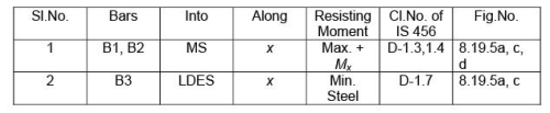
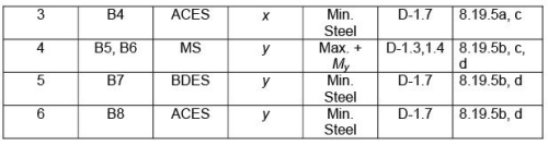
Notes: (i) MS = Middle Strip
(ii) LDES = Left Discontinuous Edge Strip
(iii) ACES = Adjacent Continuous Edge Strip
(iv) BDES = Bottom Discontinuous Edge Strip
Table 8.5 Details of eight top bars
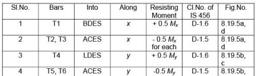
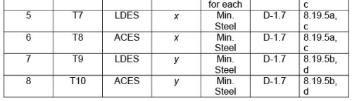
Notes: (i) MS = Middle Strip
DES = Left Discontinuous Edge Strip
(iii) ACES = Adjacent Continuous Edge Strip
(iv) BDES = Bottom Discontinuous Edge Strip
(ii) Simply supported slabs
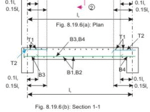
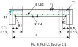
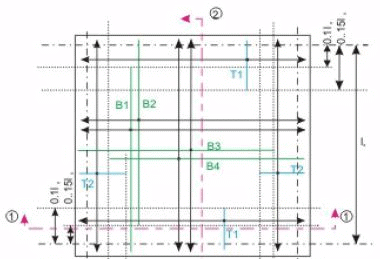
Figures 8.19.6 a, b and c present the detailing of reinforcing bars of simply supported slabs not having adequate provision to resist torsion at corners and to prevent corners from lifting. Clause D-2.1 stipulates that fifty per cent of the tension reinforcement provided at mid-span should extend to the supports. The remaining fifty per cent should extend to within 0.1lx or 0.1ly of the support, as appropriate.
8.19.8 Numerical Problems
Problem 8.2

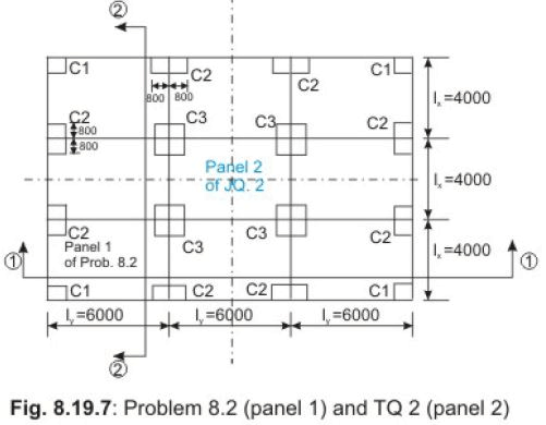
Design the slab panel 1 of Fig.8.19.7 subjected to factored live load of 8 kN/m2 in addition to its dead load using M 20 and Fe 415.
The load of floor finish is 1 kN/m2. The spans shown in figure are effective spans.
The corners of the slab are prevented from lifting.
Solution of Problem 8.2
Step 1: Selection of preliminary depth of slab
The span to depth ratio with Fe 415 is taken from cl. 24.1, Note 2 of IS 456 as 0.8 (35 + 40) / 2 = 30. This gives the minimum effective depth d = 4000/30 = 133.33 mm, say 135 mm. The total depth D is thus 160 mm.
Step 2: Design loads, bending moments and shear forces
Dead load of slab (1 m width) = 0.16(25) = 4.0 kN/m2
Dead load of floor finish (given) = 1.0 kN/m2
Factored dead load = 1.5(5) = 7.5 kN/m2
Factored live load (given) = 8.0 kN/m2
Total factored load = 15.5 kN/m2
The coefficients of bending moments and the bending moments Mx and My per unit width (positive and negative) are determined as per cl. D-1.1 and Table 26 of IS 456 for the case 4, “Two adjacent edges discontinuous” and presented in Table 8.6. The ly / lx for this problem is 6/4 = 1.5.
Table 8.6 Maximum bending moments of Problem 8.2
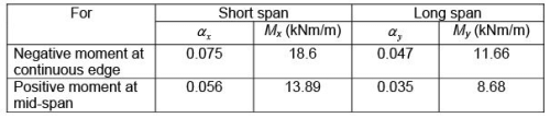
Maximum shear force in either direction is determined from Eq.8.1 (Fig.8.19.1) as
Vu = w(lx/2) = 15.5 (4/2) = 31 kN/m
Step 3: Determination/checking of the effective depth and total depth of slab
Using the higher value of the maximum bending moments in x and ydirections from Table 8.6, we get from Eq.3.25 of Lesson 5 (sec. 3.5.5):
Mu,lim = R,lim bd2
or d = [(18.6)(106)/{2.76(103)}]1/2 = 82.09 mm,
where 2.76 N/mm2 is the value of R,lim taken from Table 3.3 of Lesson 5 (sec. 3.5.5).
Since, this effective depth is less than 135 mm assumed in Step 1, we retain d = 135 mm and D = 160 mm.
Step 4: Depth of slab for shear force
Table 19 of IS 456 gives the value of τc = 0.28 N/mm2 when the lowest percentage of steel is provided in the slab. However, this value needs to be modified by multiplying with k of cl. 40.2.1.1 of IS 456. The value of k for the total depth of slab as 160 mm is 1.28. So, the value of τc is 1.28(0.28) = 0.3584 N/mm2. Table 20 of IS 456 gives τc max = 2.8 N/mm2. The computed shear stress τ v = Vu/bd = 31/135 = 0.229 N/mm2.
Since, τ v < τ c < τ c max , the effective depth of the slab as 135 mm and the total depth as 160 mm are safe.
Step 5: Determination of areas of steel
The respective areas of steel in middle and edge strips are to be determined employing Eq.3.23 of Step 5 of sec. 8.18.6 of Lesson 18. However, in Problem 8.1 of Lesson 18, it has been shown that the areas of steel computed from Eq.3.23 and those obtained from the tables of SP-16 are in good agreement. Accordingly, the areas of steel for this problem are computed from the respective Tables 40 and 41 of SP-16 and presented in Table 8.7. Table 40 of SP-16 is for the effective depth of 150 mm, while Table 41 of SP-16 is for the effective depth of 175 mm. The following results are, therefore, interpolated values obtained from the two tables of SP-16.
Table 8.7 Reinforcing bars of Problem 8.2
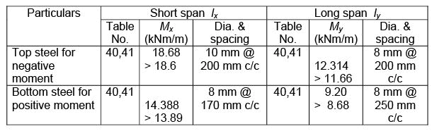
The minimum steel is determined from the stipulation of cl. 26.5.2.1 of IS 456 and is As = (0.12/100)(1000)(160) = 192 mm2 and 8 mm bars @ 250 mm c/c (= 201 mm2) is acceptable. It is worth mentioning that the areas of steel as shown in Table 8.7 are more than the minimum amount of steel.
Step 6: Selection of diameters and spacings of reinforcing bars
The advantages of using the tables of SP-16 are that the obtained values satisfy the requirements of diameters of bars and spacings. However, they are checked as ready reference here. Needless to mention that this step may be omitted in such a situation.
Maximum diameter allowed, as given in cl. 26.5.2.2 of IS 456, is 160/8 = 20 mm, which is more that the diameters used here. The maximum spacing of main bars, as given in cl. 26.3.3(1) of IS 456, is the lesser of 3(135) and 300 mm. This is also satisfied for all the bars.
The maximum spacing of minimum steel (distribution bars) is the lesser of 5(135) and 450 mm. This is also satisfied.
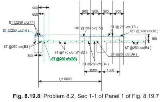
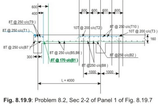
Figures 8.19.8 and 9 present the detailing of reinforcing bars.
Step 7: Determination of torsional reinforcement
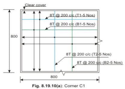
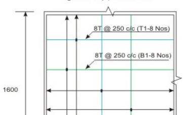
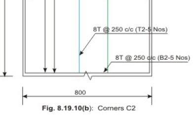
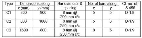
Torsional reinforcing bars are determined for the three different types of corners as explained in sec. 8.19.6 (Fig.8.19.4). The length of torsional strip is 4000/5 = 800 mm and the bars are to be provided in four layers. Each layer will have 0.75 times the steel used for the maximum positive moment. The C1 type of corners will have the full amount of torsional steel while C2 type of corners will have half of the amount provided in C1 type. The C3 type of corners do not need any torsional steel. The results are presented in
Table 8.8 and Figs.8.19.10 a, b and c.
8.19.9 Practice Questions and Problems with Answers
Q.1: Name the two types of two-way slabs.
A.1: The two types of two-way slabs are: (i) restrained slabs and (ii) simply supported slabs.
Q.2: What is the difference in the design of the two types of slabs of Q.2?
A.2: The restrained slabs are those whose corners are prevented from lifting and accordingly, there are torsional reinforcing bars in the two types of corners. The simply supported slabs do not have adequate provision to resist torsion at corners and to prevent the corners from lifting. So, torsional reinforcing bars are not provided in these slabs.
Q.3:
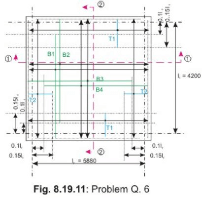
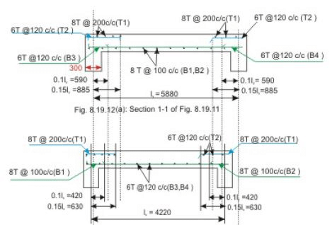
Design a two-way simply supported slab of Fig.8.19.11, not having adequate provision to resist torsion at corners and to prevent the corners from lifting. The factored live load is 6 kN/m2 and the load of the floor finish in 1 kN/m2. The spans shown in the figure are effective spans. Use M 20 and Fe 415. The width of the support is 300 mm.
A.3:
Step 1: Selection of preliminary depth of slab
As per cl.24.1, Note 2, the span to effective depth ratio = 0.8(35) = 28. The minimum effective depth = d = 4200/28 = 150 mm and, therefore, D = 175 mm.
Step 2: Design loads, bending moments and shear forces
Factored dead load of the slab = 1.5(0.175)(25) = 6.5625 kN/m2
Factored load of floor finish = 1.5(1) = 1.5 kN/m2
Factored live loads = 6.0 kN/m2
Total factored loads = 14.0625 kN/m2
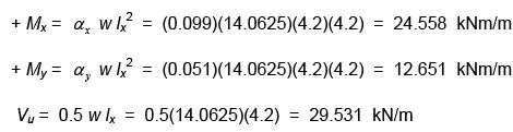
For this slab ly/lx = 5880/4200 = 1.4, Table 27 of IS 456 gives αx = 0.099 and αy = 0.051.
Step 3: Determination/checking of the effective depth and total depth of slab
d = {24.558(103)/2.76}0.5 = 94.328 mm < 150 mm
So, we keep d = 150 mm and D = 175 mm.
Step 4: Depth of slab for shear forces
Table 19 of IS 456 gives τc = 0.28 N/mm2. Clause 40.2.1.1 of IS 456 gives k = 1.25 for D = 175 mm. So, τc = (1.25)(0.28) = 0.35 N/mm2.
Table 20 of IS 456 gives τc max = 2.8 N/mm2. For this problem τv = Vu/bd= 29.531/150 = 0.1968 N/mm2. Since τv < τc < τc max , the depth is safe.
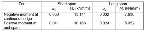
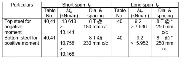
Step 5: Determination of areas of steel
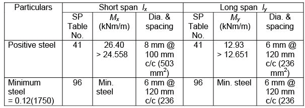
The positive steel in the two directions and the minimum steel are furnished below in Table 8.9. These are the results obtained from the use of Table 41 of SP-16.
Table 8.9 Reinforcing bars of Problem Q.6

8.19.11 Test 19 with Solutions
Maximum Marks = 50,
Maximum Time = 30 minutes
Answer all questions.
TQ.1: Design the interior panel (Panel 2) of Problem 8.2 (Fig.8.19.7). Other data are the same as those of Problem 8.2. (30 marks)
A. TQ.1: Let us keep the effective and total depths of the slab as 135 mm and 160 mm, respectively (see Problem 8.2). The total factored load = 15.5 kN/m2 (see Problem 8.2). The coefficients of bending moments and the bending moments Mx and My (positive and negative) per unit width are determined as per cl. D-1.1 and Table 26 of IS 456 for the case 1 (interior panel) and presented in Table 8.10. The ly/lx for this problem is 1.5.
Table 8.10 Bending moments of Problem TQ.2
The maximum shear force in either direction is the same as that of Problem 8.2 = 31 kN/m. Since the bending moments are much less than those of Problem 8.2, the effective depth of 135 m and total depth of 160 mm are safe. In Step 4 of solution of Problem 8.2, this depth has been found to be safe in shear. So, the depths 135 mm and 160 mm are safe.
Step 5: Determination of areas of steel
The areas of steel using the table of SP-16 are presented in Table 8.11. The maximum diameter and spacing of bars are not needed to check separately as the results obtained from tables of SP-16 already take into consideration these aspects.
Table 8.11 Reinforcing bars of Problem TQ.1
* Note: The areas of bars are selected to satisfy the minimum amount of steel. The minimum steel will be the same as that of Problem 8.2 i.e., 8 mm diameter @ 250 mm c/c. Since this is an internal panel, torsional reinforcing bars are not needed at any of the four corners.
The detailing of the bars can be drawn following the same shown in Figs.8.19.8 and 9. 8.19.12
Summary of this Lesson
This lesson explains the differences of the methods of computing shear force and bending moments of the restrained and simply supported two-way slabs. The design methods of the two types of slabs are explained avoiding the common steps of the design of one-way slabs as explained in Lesson 18. Separate diagrams for the detailing of reinforcing bars are presented to illustrate them. Torsional bars at the two types of corners of restrained slabs are illustrated. Numerical examples are solved to design and detail the reinforcements of both types of two-way slabs. Solutions of practice problems and test problems will help in understanding the complete design and detailing of the two types of two-way slabs. It would be seen that detailing would need great care and thoroughness.
FAQs on Two way Slabs - Civil Engineering (CE)
| 1. What is a two-way slab in civil engineering? |  |
| 2. How is a two-way slab different from a one-way slab? | |
| 3. What are the advantages of using a two-way slab in construction? | |
| 4. How is a two-way slab designed and analyzed? | |
| 5. What are the common types of two-way slabs used in civil engineering? | |


MCQs
,Viva Questions
,study material
,Free
,Previous Year Questions with Solutions
,Summary
,Objective type Questions
,Two way Slabs - Civil Engineering (CE)
,ppt
,Semester Notes
,mock tests for examination
,Sample Paper
,practice quizzes
,Extra Questions
,video lectures
,shortcuts and tricks
,Two way Slabs - Civil Engineering (CE)
,Important questions
,Exam
,past year papers
,Two way Slabs - Civil Engineering (CE)
;


Two way Slabs Free PDF Download
Importance of Two way Slabs
Two way Slabs Notes
Two way Slabs Civil Engineering (CE) Questions
Study Two way Slabs on the App
|
© EduRev
|
Education Revolution
|


|


within 7 days!