Total Stress Parameters

Total Stress Parameters
UU Tests:
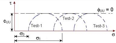
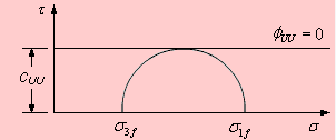
When triaxial tests are interpreted in terms of total stresses, the Mohr circles obtained from undrained undisturbed (UU) tests on identical saturated samples have the same diameter for all confining pressures. Consequently, the failure envelope obtained from these total stress Mohr circles is a horizontal straight line.

The horizontal failure envelope in total-stress coordinates can be represented by the equation shown below.
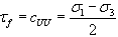
For tests in which drainage is allowed during the loading stages (for example, CU or CD tests where the first stage may be drained), the diameters of the Mohr circles plotted in total-stress space increase with confining pressure. The resulting total-stress failure envelope is then an inclined line with a non-zero vertical intercept.
It is observed that the total-stress parameters obtained from different triaxial test conditions need not be identical; for example, cCU ≠ cCD and φCU ≠ φCD. Therefore, for identical soil samples tested under different triaxial conditions (UU, CU and CD), the total-stress failure envelope is generally not unique and has limited predictive value for field conditions unless the field pore pressures are known.
Effective Stress Parameters
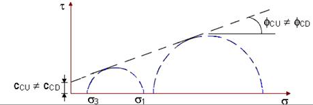
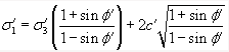
If the same triaxial test results from UU, CU and CD tests are plotted in terms of effective stresses after correcting for the measured pore water pressures, it is commonly observed that all Mohr circles at failure become tangent to a single straight failure envelope. This demonstrates that the shear strength of soil is a unique function of the effective stress acting on the failure plane.
The failure envelope in effective stress coordinates is the shear strength envelope and may be written as shown below.
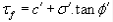
In this expression, c′ is the cohesion intercept in terms of effective stress and φ′ is the angle of shearing resistance in terms of effective stress.
If


Pore Water Pressure Parameters
The difference between total stress and effective stress is the pore water pressure u, so the total- and effective-stress Mohr circles have the same diameter but are displaced horizontally by the amount u on the σ-axis (total stress axis).
Although it is straightforward to construct a series of total-stress Mohr circles from triaxial test data, the total-stress parameters inferred in isolation have limited relevance to actual soil behaviour in the field because the actual pore water pressures in the ground under changed loading are generally unknown. To assess stability or strength in the field one needs the effective strength parameters and the corresponding pore pressure response.
In laboratory undrained triaxial tests that measure pore pressure, it is possible to determine the effective stresses directly. In drained tests, the loading must be slow enough to allow dissipation of excess pore pressure; for low-permeability soils this may require long durations.
For an undrained triaxial test the general expression relating the total pore water pressure developed (Du) to the changes in applied stresses in the two stages of the test is:
Du = Du1 + Du2 = B·Δσ3 + B·A·(Δσ1 - Δσ3) = B[Δσ3 + A(Δσ1 - Δσ3)]
where
- Du1 = pore water pressure developed in the first stage during application of confining stress Δσ3,
- Du2 = pore water pressure developed in the second stage during application of deviator stress (Δσ1 - Δσ3),
- B and A are Skempton's pore pressure parameters.
Skempton's parameters have the following typical behaviour and interpretations:
- B is primarily a function of degree of saturation: B ≈ 1 for fully saturated soils and B ≈ 0 for dry soils.
- A depends on the soil state (for example, the overconsolidation ratio) and on the magnitude of applied deviator stress. Its value at failure is required when plotting effective-stress Mohr circles from undrained tests that measure pore pressure.
Consider saturated samples in undrained triaxial tests. During the first stage, increasing the cell pressure without allowing drainage causes an increase in pore water pressure nearly equal to the applied increase in total stress; therefore there is little or no change in effective stress in this stage. During the second stage (shearing), the change in pore water pressure may be positive (increasing pore pressure) or negative (decreasing pore pressure), depending on soil type and initial state.
For UU tests on saturated soils, pore water pressure is not dissipated in either stage (i.e., Du = Du1 + Du2), so effective stresses must be found from measured pore pressures to obtain meaningful strength parameters.
For CU tests on saturated soils, pore water pressure is dissipated in the first stage (drained or partially drained), and is not dissipated only in the second stage (i.e., Du = Du2 for the shearing stage if undrained shearing is used). Thus CU tests with measured pore pressures allow determination of effective stress parameters at failure.
Stress-Strain Behaviour of Sands
Sands are usually sheared under drained conditions because of their relatively high permeability. Drained behaviour is commonly investigated in direct shear tests or in drained triaxial (CD) tests. Two of the most important parameters governing sand behaviour are the relative density (ID) and the magnitude of the effective stress σ′.
The relative density is defined (in percentage) as follows:
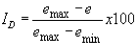
In this expression, emax and emin are the maximum and minimum void ratios determined in laboratory tests and e is the current void ratio. The expression may be written in terms of dry densities as:
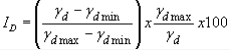
where ρdmax and ρdmin are the maximum and minimum dry densities and ρd is the current dry density. As a practical classification, sand is often described as dense if ID > 65% and loose if ID < 35%.
The influence of relative density on the drained behaviour of saturated sand can be seen from plots of CD triaxial tests conducted at the same effective confining stress: there will be no induced pore water pressure during shearing in these drained tests.
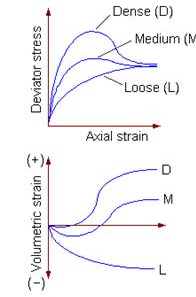
Typical observations from drained shear tests on sands of different initial densities are:
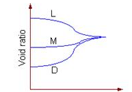
- All samples approach a similar ultimate condition of shear stress and void ratio at large strains, irrespective of initial density; however, initially dense samples often exhibit a distinct peak deviator stress (peak strength) at small axial strains whereas loose samples show a gradual increase to a lower peak or to a steady state.
- Initially dense samples tend to dilate (increase in volume) when sheared under constant confining pressure.
- Initially loose samples tend to compress (decrease in volume) when sheared.
- Dense samples usually show a higher peak angle of shearing resistance (higher peak strength) before strain softening occurs; loose samples typically do not exhibit a pronounced peak and approach the critical state more smoothly.
Worked Examples
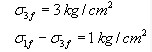
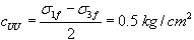
Example 1: A UU test is carried out on a saturated normally consolidated clay sample at a confining pressure of 3 kg/cm2. The deviator stress at failure is 1 kg/cm2.
(a) Determine its total-stress strength parameters.
(b) If another identical sample is tested at a confining pressure of 4 kg/cm2, what will be the vertical axial stress at failure?
Solution:
(a)
From the horizontal failure envelope for UU total-stress interpretation, φUU = 0.
(b)
UU tests on identical samples give the same failure deviator stress irrespective of the confining pressure. Therefore the deviator stress at failure remains 1 kg/cm2.

The vertical axial stress at failure (σ1) is the sum of confining pressure σ3 and deviator stress (σ1 - σ3):
Hence, for σ3 = 4 kg/cm2,
σ1 = 4 + 1 = 5 kg/cm2.
Example 2: Results of triaxial tests conducted on two saturated clay samples are given. Determine the shear strength parameters.

Sample data:
Sample1 Sample2
Confining pressure: 4.8 kg/cm2 6.3 kg/cm2
Axial stress at failure: 6.8 kg/cm2 9.3 kg/cm2
Pore water pressure at failure: 3.8 kg/cm2 4.8 kg/cm2
Solution:
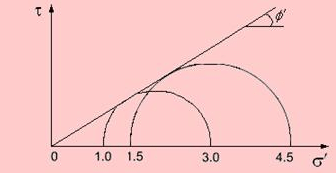
For each sample, compute the total stresses at failure and then subtract the pore pressure to obtain the effective stresses. Plotting the effective-stress Mohr circles (as shown) and drawing the common tangent gives the effective stress shear strength parameters (c′ and φ′).
For Sample 1:
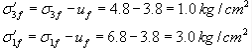
For Sample 2:
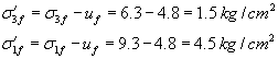
From the effective-stress Mohr plot one can obtain the following parameters at failure:

Summary
This chapter emphasises the distinction between total-stress and effective-stress interpretations of triaxial test data. Total-stress parameters obtained from UU tests can be misleading for field problems unless pore pressures are known. Effective-stress parameters, obtained either by measuring pore pressure in undrained tests or by performing drained tests, provide a unique and physically meaningful description of shear strength. Skempton's parameters A and B are central to relating changes in applied stress to pore pressure development in undrained conditions. The stress-strain response of sands depends strongly on relative density and effective stress; dense sands often dilate and show peak strengths, whereas loose sands compress and have different stress-strain paths.
FAQs on Total Stress Parameters
| 1. What are the different stress parameters considered in civil engineering? |  |
| 2. How is axial stress calculated in civil engineering? | |
| 3. What is shear stress and how is it determined in civil engineering? | |
| 4. How is bending stress calculated for beams in civil engineering? | |
| 5. What is bearing stress and how is it computed in civil engineering? | |


