Ductility and Deflections
→ Ductility
o Toughness, deformability, energy absorption capacity
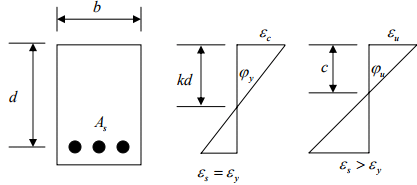
o For beams failing in flexure the ductility ratio can be defined as the ratio of the curvature at ultimate moment to the curvature at yield.
→ Yield condition: 
→ Ultimate condition: 
→ Ductility =
→ The ratio gives a measure of the curvature ductility of the cross section.
o Ductility characterizes the deformation capacity of members (structures) after yielding, or their ability to dissipate energy.
o In general, ductility is a structural property which is governed by fracture and depends on structure size.
o The defined ductility (ratio) shown above does not give information about effects of a moderate number of cycles nor about the shape of the descending branch in moment-rotation curves.
o For doubly reinforced cross section,
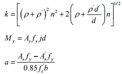
and the curvature ductility ratio factor is given

o Effect of axial load on flexural ductility
Ductility of unconfined column sections:
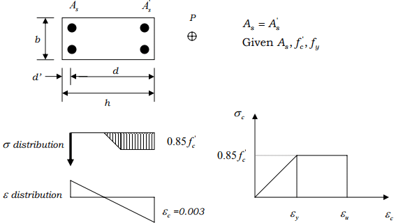
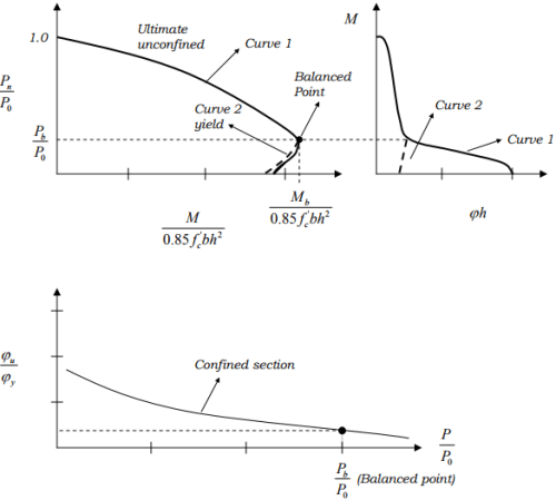
Curve 1: Combinations of P and M and ϕh that cause the column to reach εu (ultimate concrete strain) without confinement
Curve 2: Combinations of P and M and ϕh at which the tension steel first reaches the yield strength.
→ The difference between Curve 1 and 2 indicates the amount of inelastic bending deformation (energy absorption), which occurs once the yielding starts.
(P0 = pure axial strength.)
→ Ductility is reduced by the presence of axial load.
Because of the brittle behavior of unconfined columns it is recommended that the ends of the columns in frames in earthquake regions be confined by closely spaced transverse reinforcement when, generally, . P > 0.4P0
o Effect of confinement
→ If the compression zone is confined by ties, hoops, and spirals, ductility will be improved.
→ Additional confinement due to loading and support conditions.
o Displacement ductility factor
A measure of the ductility of a structure may be defined by the displacement ductility factor.

where ∆u = the lateral deflection at the end of the post-elastic range,
and ∆y = the lateral deflection when yield is first reached.
o For column members, factors affecting the ductility, other than those related to confinement, are:
→ rate of loading
→ concrete strength
→ bar diameter
→ content of longitudinal steel
→ yield strength of the transverse steel
» Deflections
o Types of deflection
1. Immediate deflections (short-term)
– Deflections that occur at once upon application of load.
– Time-independent
– Elastic-plastic
2. Long-term deflections
– Deflections that occur due to time-dependent behavior of materials, mainly creep and shrinkage.
– Creep (under sustained loading)
– Shrinkage (independent of loading)
» Short-term deflection
o Effective moment of inertia
Consider a beam structure subjected to bending deflection,
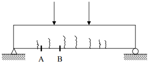
The deflection angle between A and B is

where ϕ = curvature
Due the existence of cracks, the effective moment of inertia will be calculated as

where Mmax = moment capacity of the cross section,
Mcr = moment capacity at first cracking,
Ig = moment of inertia of gross section, and
Icr = moment of inertia of cracked section.
It is known that c

where fcr = maximum stress at cracking,
y = maximum distance from N.A. to the outer-most fibre on the cross section.
» Long-term deflection
o The member when loaded undergoes an immediate deflection. The additional deflections are caused due to creep and shrinkage. The rate of these additional deflections decreases by time.
o Effect of creep on the flexure behavior of concrete member
→ Concrete creep results in a shortening of the compressed part of the concrete cross section, hence causes additional curvature and stress redistribution in the section.
→ Effective modulus of elasticity considering creep:
For stress less than 

where Ec= modulus of elasticity at the instant of loading.

The effective modulus including creep is

o Effect of shrinkage on the flexure behavior of concrete member
Concrete sections reinforced symmetrically causes uniform stress distribution. In unsymmetrical sections a non-uniform stress distribution, and hence, a curvature is resulted.
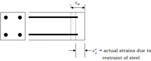
Concrete will tend to shrink, but cannot due to the steel restraint, hence concrete undergoes tensile stress and steel reinforcement will be in compression.
Effective concrete stress considering creep and shrinkage:
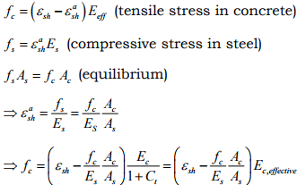
where Ac = area of concrete, εsh = free shrinkage of concrete εsha = actual shrinkage of concrete
As = area of steel,
Es = Young’s modulus of steel, and
Ec = Young’s modulus of concrete.
This tensile stress, fc , may exceed the tensile strength of concrete causing cracking.
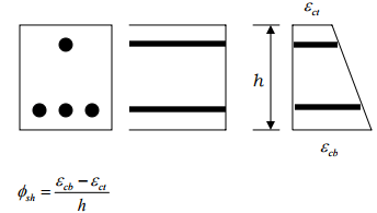
→ Note that for symmetrical reinforcement the curvature is zero, due to shrinkage. Otherwise,
» Simplified approach in computing long-term deflections:
→ Due to complexities, for traditional applications simplified methods are used.
→ Computer based analysis can be performed with effective E modulus to predict long-term deflection, taking into account the load history.
» Control of deflections
o Excessive deflections can lead to cracking of supported walls and partitions, ill-fitting doors and windows, poor roof drainage, misalignment of sensitive machinery and equipment, or visually offensive sag, and interfere with service conditions.
o The need for deflection control
1. Sensory acceptability
2. Serviceability of the structure
3. Effect on nonstructural elements
4. Effect on structural elements
o Control strategies of deflections
1. Limiting span/thickness ratios Deflections are controlled by setting suitable upper limits on the span-depth ratio of members.
2. Limiting computed deflections Deflections are controlled by calculating predicted deflections and comparing those with specific limitations that may be imposed by codes or by special requirements.
→ In any case, maximum allowable deflections are constrained by structural and functional limitations.
o Some permissible deflections by ACI Code
Minimum thickness of beams:
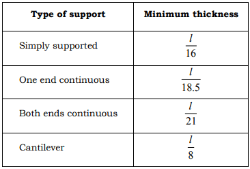
PS: Clear span l in inches.
o Additional long-term deflection multipliers

where ξ = a time-dependent coefficient characterizing material properties, and 
→ Long-term deflection ∆total = λ∆immediate


