Indeterminate Trusses & Industrial Frames - 2 | Structural Analysis - Civil Engineering (CE) PDF Download

Example 35.2
Determine bar forces in the 3-panel truss of the previous example (shown in Fig. 35.2a) assuming that the diagonals can carry only tensile forces.
Solution:
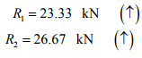
In this case, the load carried by the compressive diagonal member is zero. Hence the panel shear is completely resisted by the tension diagonal. Reactions of the truss are the same as in the previous example and is given by,
 (1)
(1)
Consider again the equilibrium of free body diagram of the truss shown left of A − A. This is shown in Fig. 35.3a.
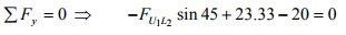
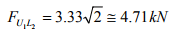
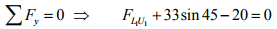
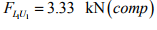
Applying ∑ Fy = 0,
 (2)
(2)
It is easily seen that, 
Considering the vertical equilibrium of joint L0, we ge
 (3)
(3)
Since diagonals are inclined at 45° to the horizontal, the vertical and horizontal components of forces are equal in any panel.
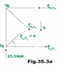
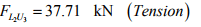
Now consider equilibrium of truss left of section C−C (ref. Fig. 35.3b)
In this panel, the shear is 3.33 kN. Considering the vertical equilibrium of the free body diagram,
 (4)
(4)

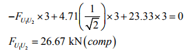
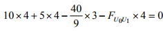
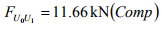
Taking moment of all forces about U1,
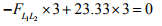
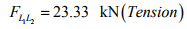 (6)
(6)
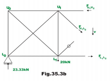
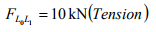
Considering the joint equilibrium of L1 (ref. Fig. 35.3c), yields
 (7)
(7)
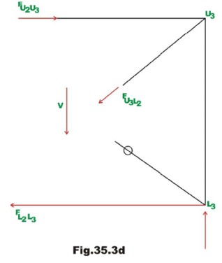
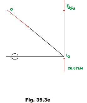
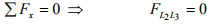
Considering the equilibrium of right side of the section B − B (ref. Fig. 35.3d) the forces in the 3rd panel are evaluated.
 (11)
(11)
 (12)
(12)

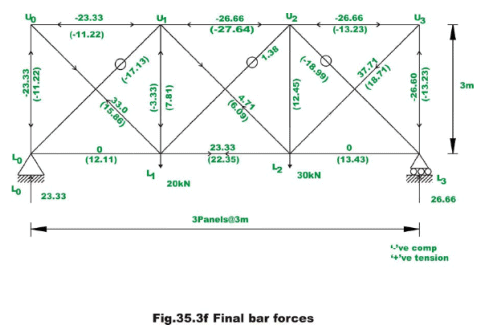
The complete solution is shown in Fig. 35.3f. Also in the diagram, bar forces obtained by exact method are shown in brackets.
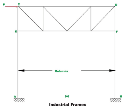
Industrial frames and portals
Common types of industrial frames are shown in Fig. 35.4a and 35.4b. They consist of two columns and a truss placed over the columns. They may be subjected to vertical loads and wind loads (horizontal loads). While analyzing for the gravity loads, it is assumed that the truss is simply supported on columns. However, while analyzing the frame for horizontal loads it is assumed that, the truss is rigidly connected to columns. The base of the column are either hinged or fixed depending on the column foundation. When the concrete footing at the column base is small, then it is reasonable to assume that the columns are hinged at the base. However if the column are built into massive foundation, then the column ends are considered as fixed for the analysis purposes.

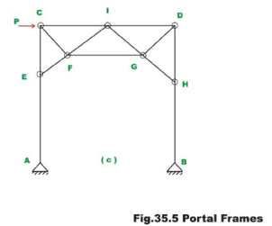
Before considering the analysis of structures to wind load (horizontal load) consider the portals which are also used as the end portals of bridge structure (see Fig. 35.5). Their behaviour is similar to industrial trusses. The portals are also assumed to be fixed or hinged at the base depending on the type of foundation.
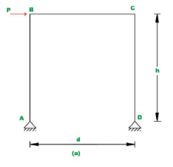
Consider a portal which is hinged at the base, as shown in Fig. 35.5a. This structure is statically indeterminate to degree one. To analyse this frame when subjected to wind loads by only equations of statics, it is required to make one assumption. When stiffness of columns is nearly equal then it is assumed that the shear at the base of each column is equal. If stiffness of columns is unequal then it is assumed that the shear at the base of a column is proportional to its stiffness.
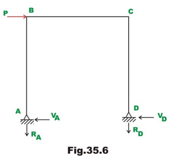
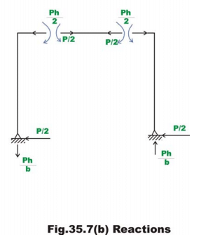
Reactions and Bending moments:
As per the assumption, shear at the base of columns is given by (vide Fig. 35.6)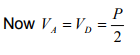
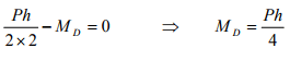
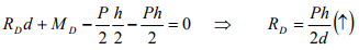
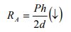
Taking moment about hinge D ,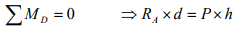
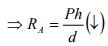
And 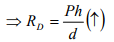
The bending moment diagram is shown in Fig. 35.7.
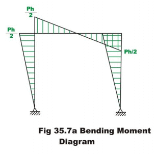
It is clear from the moment diagram, an imaginary hinge forms at the mid point of the girders. Thus instead of making assumption that the shear is equal at the column base, one could say that a hinge forms at the mid point of the girder. Both the assumptions are one and the same.
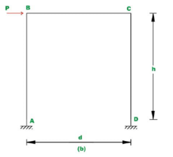
Now consider a portal frame which is fixed at the base as shown in Fig. 35.5b. This is statically indeterminate to third degree and one needs to make three independent assumptions to solve this problem by equations of static equilibrium alone. Again it is assumed that the shear at the base of each column is equal provided their stiffnesses are equal. The deformed shape of the portal is shown in Fig. 35.8a and the deformed shape of the industrial frame is shown in Fig.35.8b.
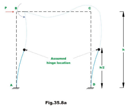
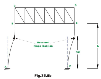
In such a case, the bending moment at the base of the column (at A) produces tension on outside fibres of column cross section. The bending moment at top of column produces tension on inside fibres of column. Hence bending moment changes its sign between column base and top. Thus bending moment must be zero somewhere along the height of the portal. Approximately the inflexion point occurs at the mid height of columns. Now we have three independent assumptions and using them, we could evaluate reactions and moments. In the case of industrial frames, the inflexion points are assumed to occur at mid height between A and B .
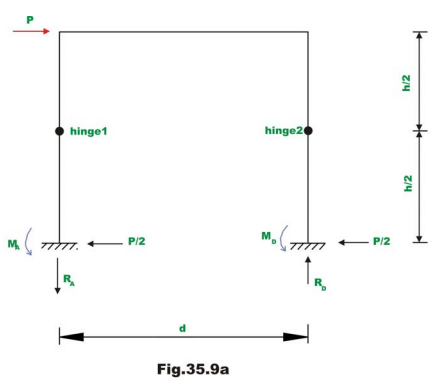
Taking moment of all forces left of hinge 1 about hinge 1 (vide Fig. 35.9a),yields
Similarly taking moment of all forces left of hinge 2 about hinge 2,
Taking moment of all forces right of hinge 1 about hinge 1 gives,
Similarly
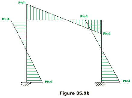
The bending moment diagram is shown in Fig. 35.9b.
If the base of the column is partially fixed then hinge is assumed at a height of 1/3rd from the base. Note that when it is hinged at the base of the column, the inflexion point occurs at the support and when it is fixed, the inflexion point occurs at mid-height.
Example 35.3
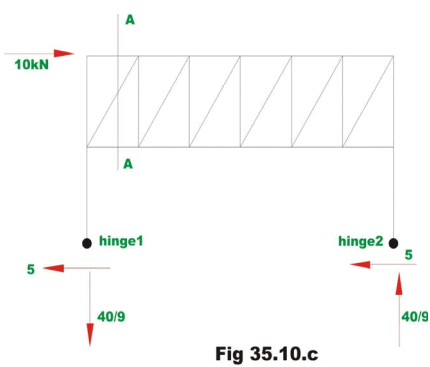
Determine approximately forces in the member of a truss portal shown in Fig. 35.10a.

Taking moment of all forces right of hinge 2 about hinge 2, results
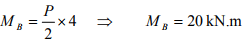 (2)
(2)
Similarly MA = kN.m 20 (3)
Taking moment of all forces right of hinge 1 about hinge 1 gives,
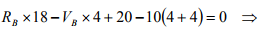
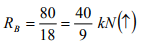
Similarly,
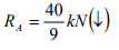 (4)
(4)
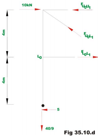
Forces in the truss member can be calculated either by method of sections or by method of joints. For example, consider the equilibrium of truss left of A − Aas shown in Fig. 35.10d.
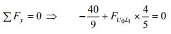
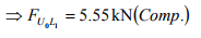 (5)
(5)
Taking moment about , U0,
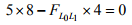
 (6)
(6)
Taking moment about L1,
 (7)
(7)
Summary
It is observed that prior to analysis of indeterminate structures either by stiffness method or force method; one must have information regarding their relative stiffnesses and member material properties. This information is not available prior to preliminary design of structures. Hence in such cases, one can not perform indeterminate structural analysis by exact methods. Hence, usually in such cases, based on few approximations (which are justified on the structural behaviour under the applied loads) the indeterminate structures are reduced into determinate structures. The determinate structure is then solved by equations of statics. This methodology has been adopted in this lesson to solve indeterminate trusses and industrial frames. Depending upon the validity of assumptions, the results of approximate methods compare favourably with exact methods of structural analysis as seen from the numerical examples.
|
32 videos|154 docs|31 tests
|
FAQs on Indeterminate Trusses & Industrial Frames - 2 - Structural Analysis - Civil Engineering (CE)
| 1. What are indeterminate trusses and industrial frames? |  |
| 2. How do indeterminate trusses differ from determinate trusses? | |
| 3. Why are indeterminate trusses and industrial frames commonly used in civil engineering? | |
| 4. How are indeterminate trusses and industrial frames analyzed? | |
| 5. What are the challenges associated with analyzing indeterminate trusses and industrial frames? | |


Objective type Questions
,past year papers
,Exam
,MCQs
,ppt
,practice quizzes
,Extra Questions
,Viva Questions
,Important questions
,Indeterminate Trusses & Industrial Frames - 2 | Structural Analysis - Civil Engineering (CE)
,Sample Paper
,Previous Year Questions with Solutions
,mock tests for examination
,Summary
,Semester Notes
,shortcuts and tricks
,Free
,video lectures
,study material
,Indeterminate Trusses & Industrial Frames - 2 | Structural Analysis - Civil Engineering (CE)
,Indeterminate Trusses & Industrial Frames - 2 | Structural Analysis - Civil Engineering (CE)
;


Indeterminate Trusses & Industrial Frames - 2 Free PDF Download
Importance of Indeterminate Trusses & Industrial Frames - 2
Indeterminate Trusses & Industrial Frames - 2 Notes
Indeterminate Trusses & Industrial Frames - 2 Civil Engineering (CE) Questions
Study Indeterminate Trusses & Industrial Frames - 2 on the App
|
© EduRev
|
Education Revolution
|


|


within 7 days!