Design of Riveted Joints | Design of Machine Elements - Mechanical Engineering PDF Download
Strength of riveted joint:
Strength of a riveted joint is evaluated taking all possible failure paths in the joint into account. Since rivets are arranged in a periodic manner, the strength of joint is usually calculated considering one pitch length of the plate. There are four possible ways a single rivet joint may fail.
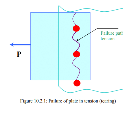
a) Tearing of the plate:
If the force is too large, the plate may fail in tension along the row (see figure 10.2.1). The maximum force allowed in this case is
P1=st (p-d) t
where
st = allowable tensile stress of the plate material
p = pitch
d = diameter of the rivet hole
t = thickness of the plate
b) Shearing of the rivet:
The rivet may shear as shown in figure 10.2.2.
The maximum force withstood by the joint to prevent this failure is
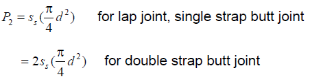
where ss =allowable shear stress of the rivet material.
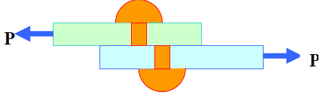
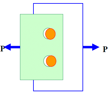
c) Crushing of rivet:
If the bearing stress on the rivet is too large the contact surface between the rivet and the plate may get damaged. (see figure 10.2.3). With a simple assumption of uniform contact stress the maximum force allowed is
P3 = sc dt
where sc =allowable bearing stress between the rivet and plate material.
PFigure 10.2.3: Failure of rivets by
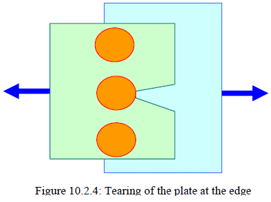
d) Tearing of the plate at edge: If the margin is too small, the plate may fail as shown in figure 10.2.4. To prevent the failure a minimum margin of m =1.5d is usually provided.
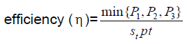
Efficiency:
Efficiency of the single riveted joint can be obtained as ratio between the maximum of P1, P2 and P3 and the load carried by a solid plate which is Stpt . Thus
In a double or triple riveted joint the failure mechanisms may be more than those discussed above. The failure of plate along the outer row may occur in the same way as above. However, in addition the inner rows may fail. For example, in a double riveted joint, the plate may fail along the second row. But in order to do that the rivets in the first row must fail either by shear or by crushing. Thus the maximum allowable load such that the plate does not tear in the second row is P4 = st(p-d)t + min {P2,P3}
Further, the joint may fail by
(i) shearing of rivets in both rows
(ii) crushing of rivets in both rows
(iii) shearing of rivet in one row and crushing in the other row.
The efficiency should be calculated taking all possible failure mechanism into consideration.
Design of rivet joints:
The design parameters in a riveted joints are d , p and m.
Diameter of the hole ( d ): When thickness of the plate (t ) is more than 8 mm, Unwin’s formula is used,
d = 6 √t mm.
Otherwise d is obtained by equating crushing strength to the shear strength of the joint. In a double riveted zigzag joint, this implies
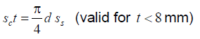
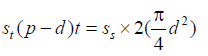
However, d should not be less than t , in any case. The standard size of d is tabulated in code IS: 1928-1961. Pitch ( p ): Pitch is designed by equating the tearing strength of the plate to the shear strength of the rivets. In a double riveted lap joint, this takes the following form.
But p ≥ 2d in order to accommodate heads of the rivets.
Margin (m ): m =1.5 d.
In order to design boiler joints, a designer must also comply with Indian Boiler Regulations (I.B.R.).
( pb : usually 0.33p+ 0.67 d mm)
|
49 videos|70 docs|77 tests
|
FAQs on Design of Riveted Joints - Design of Machine Elements - Mechanical Engineering
| 1. What are riveted joints in mechanical engineering? |  |
| 2. What are the advantages of using riveted joints? | |
| 3. Are there any limitations or disadvantages of using riveted joints? | |
| 4. How can the strength of a riveted joint be calculated? | |
| 5. Are there any alternative methods to riveted joints in mechanical engineering? | |

|
4.97/5 Rating |

|
Dec 22, 2024 Last updated |

|
Explore Courses for Mechanical Engineering exam
|
|
Previous Year Questions with Solutions
,ppt
,Design of Riveted Joints | Design of Machine Elements - Mechanical Engineering
,MCQs
,Extra Questions
,study material
,shortcuts and tricks
,mock tests for examination
,Free
,practice quizzes
,Important questions
,Viva Questions
,Objective type Questions
,Exam
,Design of Riveted Joints | Design of Machine Elements - Mechanical Engineering
,Semester Notes
,Summary
,Design of Riveted Joints | Design of Machine Elements - Mechanical Engineering
,past year papers
,Sample Paper
,video lectures
;


Design of Riveted Joints Free PDF Download
Importance of Design of Riveted Joints
Design of Riveted Joints Notes
Design of Riveted Joints Mechanical Engineering Questions
Study Design of Riveted Joints on the App
|
© EduRev
|
Education Revolution
|


|


