Forces | Engineering Mechanics - Civil Engineering (CE) PDF Download
| Table of contents |
|
| An Overview |
|
| Causes of force |
|
| Mathematical Representation of a Force |
|
| Measuring Forces |
|
| Force Laws |
|
| Electrostatic Forces |
|
| Electromagnetic Forces |
|

An Overview
In this chapter we review the basic concepts of forces, and force laws. Most of this material is identical to material covered in EN030, and is provided here as a review.
Definition of a Force
Engineering design calculations nearly always use classical (Newtonian) mechanics. In classical mechanics, the concept of a `force’ is based on experimental observations that everything in the universe seems to have a preferred configuration – masses appear to attract each other; objects with opposite charges attract one another; magnets can repel or attract one another; you are probably repelled by your professor. But we don’t really know why this is (except perhaps the last one).
The idea of a force is introduced to quantify the tendency of objects to move towards their preferred configuration. If objects accelerate very quickly towards their preferred configuration, then we say that there’s a big force acting on them. If they don’t move (or move at constant velocity), then there is no force. We can’t see a force; we can only deduce its existence by observing its effect.
Specifically, forces are defined through Newton’s laws of motion
0. A `particle’ is a small mass at some position in space.
1. When the sum of the forces acting on a particle is zero, its velocity is constant;
2. The sum of forces acting on a particle of constant mass is equal to the product of the mass of the particle and its acceleration;
3. The forces exerted by two particles on each other are equal in magnitude and opposite in direction.
The second law provides the definition of a force – if a mass m has acceleration a, the force F acting on it is
Of course, there is a big problem with Newton’s laws – what do we take as a fixed point (and orientation) in order to define acceleration? The general theory of relativity addresses this issue rigorously. But for engineering calculations we can usually take the earth to be fixed, and happily apply Newton’s laws. In rare cases where the earth’s motion is important, we take the stars far from the solar system to be fixed.
Causes of force
Forces may arise from a number of different effects, including
(i) Gravity;
(ii) Electromagnetism or electrostatics;
(iii) Pressure exerted by fluid or gas on part of a structure
(v) Wind or fluid induced drag or lift forces;
(vi) Contact forces, which act wherever a structure or component touches anything;
(vii) Friction forces, which also act at contacts.
Some of these forces can be described by universal laws. For example, gravity forces can be calculated using Newton’s law of gravitation; electrostatic forces acting between charged particles are governed by Coulomb’s law; electromagnetic forces acting between current carrying wires are governed by Ampere’s law; buoyancy forces are governed by laws describing hydrostatic forces in fluids. Some of these universal force laws are listed in Section 2.6.
Some forces have to be measured. For example, to determine friction forces acting in a machine, you may need to measure the coefficient of friction for the contacting surfaces. Similarly, to determine aerodynamic lift or drag forces acting on a structure, you would probably need to measure its lift and drag coefficient experimentally. Lift and drag forces are described in Section 2.6. Friction forces are discussed in Section 12.
Contact forces are pressures that act on the small area of contact between two objects. Contact forces can either be measured, or they can be calculated by analyzing forces and deformation in the system of interest. Contact forces are very complicated, and are discussed in more detail in Section 8.
Units of force and typical magnitudes
In SI units, the standard unit of force is the Newton, given the symbol N.
The Newton is a derived unit, defined through Newton’s second law of motion – a force of 1N causes a 1 kg mass to accelerate at 1 ms−2.
The fundamental unit of force in the SI convention is kg m/s2
In US units, the standard unit of force is the pound, given the symbol lb or lbf (the latter is an abbreviation for pound force, to distinguish it from pounds weight)
A force of 1 lbf causes a mass of 1 slug to accelerate at 1 ft/s2
US units have a frightfully confusing way of representing mass – often the mass of an object is reported as weight, in lb or lbm (the latter is an abbreviation for pound mass). The weight of an object in lb is not mass at all – it’s actually the gravitational force acting on the mass. Therefore, the mass of an object in slugs must be computed from its weight in pounds using the formula
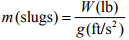
where g=32.1740 ft/s2 is the acceleration due to gravity.
A force of 1 lb(f) causes a mass of 1 lb(m) to accelerate at 32.1740 ft/s2
The conversion factors from lb to N are
| 1 lb | = | 4.448 N |
| 1 N | = | 0.2248 lb |
As a rough guide, a force of 1N is about equal to the weight of a medium sized apple. A few typical force magnitudes (from `The Sizesaurus’, by Stephen Strauss, Avon Books, NY, 1997) are listed in the table below
Force | Newtons | Pounds Force |
Gravitational Pull of the Sun on Earth | 3.5 x10²² | 7.9 x10²¹ |
Gravitational Pull of the Earth on the Moon | 2 x10²⁰ | 4.5 x10¹⁹ |
Thrust of a Saturn V rocket engine | 3.3 x10⁷ | 7.4 x10⁶ |
Thrust of a large jet engine | 7.7 x10⁵ | 1.7 x10⁵ |
Pull of a large locomotive | 5 x10⁵ | 1.1x10⁵ |
Force between two protons in a nucleus | 104 | 103 |
Gravitational pull of the earth on a person | 7.3 x10² | 1.6 x10² |
Maximum force exerted upwards by a forearm | 2.7 x10² | 60 |
Gravitational pull of the earth on a 5 cent coin | 5.1x10⁻² | 1.1 x10⁻² |
Force between an electron and the nucleus of a Hydrogen atom | 8 x10⁻⁶ | 1.8 x10⁻⁸ |
Classification of forces: External forces, constraint forces and internal forces.
When analyzing forces in a structure or machine, it is conventional to classify forces as external forces; constraint forces or internal forces.
External forces arise from interaction between the system of interest and its surroundings.
Examples of external forces include gravitational forces; lift or drag forces arising from wind loading; electrostatic and electromagnetic forces; and buoyancy forces; among others. Force laws governing these effects are listed later in this section.
Constraint forces are exerted by one part of a structure on another, through joints, connections or contacts between components. Constraint forces are very complex, and will be discussed in detail in Section 8.
Internal forces are forces that act inside a solid part of a structure or component. For example, a stretched rope has a tension force acting inside it, holding the rope together. Most solid objects contain very complex distributions of internal force. These internal forces ultimately lead to structural failure, and also cause the structure to deform. The purpose of calculating forces in a structure or component is usually to deduce the internal forces, so as to be able to design stiff, lightweight and strong components. We will not, unfortunately, be able to develop a full theory of internal forces in this course – a proper discussion requires understanding of partial differential equations, as well as vector and tensor calculus. However, a brief discussion of internal forces in slender members will be provided in Section 9.
Mathematical Representation of a Force
Force is a vector – it has a magnitude (specified in Newtons, or lbf, or whatever), and a direction.
A force is therefore always expressed mathematically as a vector quantity. To do so, we follow the usual rules, which are described in more detail in the vector tutorial. The procedure is
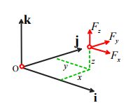
1. Choose basis vectors {i, j, k} or {e1, e2, e2} that establish three fixed (and usually perpendicular) directions in space;
2. Using geometry or trigonometry, calculate the force component along each of the three reference directions (Fx, Fy, Fz) or (F1, F2, F3) ;
3. The vector force is then reported as
F = Fx i + Fy j + Fz k = F1e1 + F2e2 + F3e3 (appropriate units)
For calculations, you will also need to specify the point where the force acts on your system or structure. To do this, you need to report the position vector of the point where the force acts on the structure.
The procedure for representing a position vector is also described in detail in the vector tutorial. To do so, you need to:
1. Choose an origin
2. Choose basis vectors {i, j, k} or {e1, e2, e2} that establish three fixed directions in space (usually we use the same basis for both force and position vectors) (rx, ry,rz) or (r1,r2,r3)
4. The position vector is then reported as
r = rxi + ryj + rzk = r1e1+ r2e2 + r3,e3 (appropriate units)
Measuring Forces
Engineers often need to measure forces. According to the definition, if we want to measure a force, we need to get hold of a 1 kg mass, have the force act on it somehow, and then measure the acceleration of the mass. The magnitude of the acceleration tells us the magnitude of the force; the direction of motion of the mass tells us the direction of the force. Fortunately, there are easier ways to measure forces.
In addition to causing acceleration, forces cause objects to deform – for example, a force will stretch or compress a spring; or bend a beam. The deformation can be measured, and the force can be deduced.
The simplest application of this phenomenon is a spring scale. The change in length of a spring is proportional to the magnitude of the force causing it to stretch (so long as the force is not too large!)– this relationship is known as Hooke’s law and can be expressed as an equation
kδ = F
where the spring stiffness k depends on the material the spring is made from, and the shape of the spring. The spring stiffness can be measured experimentally to calibrate the spring.
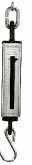
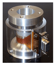
Spring scales are not exactly precision instruments, of course. But the same principle is used in more sophisticated instruments too. Forces can be measured precisely using a `force transducer’ or `load cell’ (A search for `force transducer’ on any search engine will bring up a huge variety of these – a few are shown in the picture). The simplest load cell works much like a spring scale – you can load it in one direction, and it will provide an electrical signal proportional to the magnitude of the force. Sophisticated load cells can measure a force vector, and will record all three force components. Really fancy load cells measure both force vectors, and torque or moment vectors.
Simple force transducers capable of measuring a single force component. The instrument on the right is called a `proving ring’ – there’s a short article describing how it works at

A sophisticated force transducer produced by MTS systems, which is capable of measuring forces and moments acting on a car’s wheel in-situ.
The basic design of all these load cells is the same – they measure (very precisely) the deformation in a part of the cell that acts like a very stiff spring.
In this case the `spring’ is actually a tubular piece of high-strength steel. When a force acts on the cylinder, its length decreases slightly. The deformation is detected using `strain gages’ attached to the cylinder. A strain gage is really just a thin piece of wire, which deforms with the cylinder. When the wire gets shorter, its electrical resistance decreases – this resistance change can be measured, and can be used to work out the force. It is possible to derive a formula relating the force to the change in resistance, the load cell geometry, and the material properties of steel, but the calculations involved are well beyond the scope of this course.
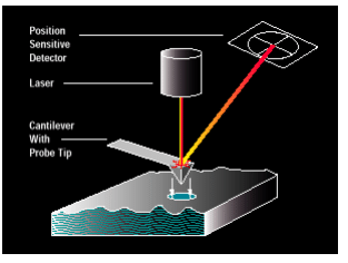
The most sensitive load cell currently available is the atomic force microscope (AFM) – which as the name suggests, is intended to measure forces between small numbers of atoms. This device consists of a very thin (about 1 μm) cantilever beam, clamped at one end, with a sharp tip mounted at the other. When the tip is brought near a sample, atomic interactions exert a force on the tip and cause the cantilever to bend. The bending is detected by a laser-mirror system. The device is capable of measuring forces of about 1 pN (that’s 10−12 N!!), and is used to explore the properties of surfaces, and biological materials such as DNA strands and cell membranes.
Selecting a load cell
As an engineer, you may need to purchase a load cell to measure a force. Here are a few considerations that will guide your purchase.
1. How many force (and maybe moment) components do you need to measure? Instruments that measure several force components are more expensive…
2. Load capacity – what is the maximum force you need to measure?
3. Load range – what is the minimum force you need to measure?
4. Accuracy
5. Temperature stability – how much will the reading on the cell change if the temperature changes?
6. Creep stability – if a load is applied to the cell for a long time, does the reading drift?
7. Frequency response – how rapidly will the cell respond to time varying loads? What is the maximum frequency of loading that can be measured?
8. Reliability
9. Cost
Force Laws
In this section, we list equations that can be used to calculate forces associated with
(i) Gravity
(ii) Forces exerted by linear springs
(iii) Electrostatic forces
(iv) Electromagnetic forces
(v) Hydrostatic forces and buoyancy
(vi) Aero- and hydro-dynamic lift and drag forces
Gravitation
Gravity forces acting on masses that are a large distance apart Consider two masses m1 and m2 that are a distance d apart. Newton’s law of gravitation states that mass m1 will experience a force

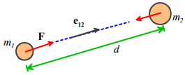
where e12 is a unit vector pointing from mass m1 to mass m2 , and G is the Gravitation constant. Mass m2 will experience a force of equal magnitude, acting in the opposite direction.
In SI units, G = 6.673×10⁻¹¹ m3kg -1s-2
The law is strictly only valid if the masses are very small (infinitely small, in fact) compared with d – so the formula works best for calculating the force exerted by one planet or another; or the force exerted by the earth on a satellite.
Gravity forces acting on a small object close to the earth’s surface
For engineering purposes, we can usually assume that
1. The earth is spherical, with a radius R
2. The object of interest is small compared with R
3. The object’s height h above the earths surface is small compared to R
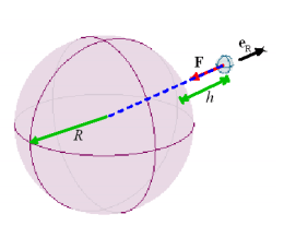
If the first two assumptions are valid, then one can show that Newton’s law of gravitation implies that a mass m at a height h above the earth’s surface experiences a force
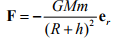
where M is the mass of the earth; m is the mass of the object; R is the earth’s radius, G is the gravitation constant and er is a unit vector pointing from the center of the earth to the mass m. (Why do we have to show this? Well, the mass m actually experiences a force of attraction towards every point inside the earth. One might guess that points close to the earth’s surface under the mass would attract the mass more than those far away, so the earth would exert a larger gravitational force than a very small object with the same mass located at the earth’s center. But this turns out not to be the case, as long as the earth is perfectly uniform and spherical).
If the third assumption (h<<R) is valid, then we can simplify the force law by setting
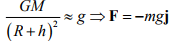
where g is a constant, and j is a `vertical’ unit vector (i.e. perpendicular to the earth’s surface).
In SI units g = 9.81ms−2 .
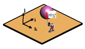
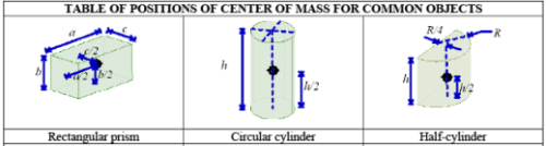
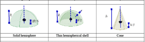
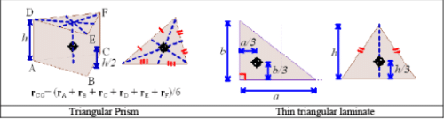
The force of gravity acts at the center of gravity of an object. For most engineering calculations the center of gravity of an object can be assumed to be the same as its center of mass. For example, gravity would exert a force at the center of the sphere that Mickey is holding. The location of the center of mass for several other common shapes is shown below. The procedure for calculating center of mass of a complex shaped object is discussed in more detail in section 6.3.
Some subtleties about gravitational interactions
There are some situations where the simple equations in the preceding section don’t work. Surveyors know perfectly well that the earth is no-where near spherical; its density is also not uniform. The earth’s gravitational field can be quite severely distorted near large mountains, for example. So using the simple gravitational formulas in surveying applications (e.g. to find the `vertical’ direction) can lead to large errors.
Also, the center of gravity of an object is not the same as its center of mass. Gravity is actually a distributed force. When two nearby objects exert a gravitational force on each other, every point in one body is attracted towards every point inside its neighbor. The distributed force can be replaced by a single, statically equivalent force, but the point where the equivalent force acts depends on the relative positions of the two objects, and is not generally a fixed point in either solid. One consequence of this behavior is that gravity can cause rotational accelerations, as well as linear accelerations. For example, the resultant force of gravity exerted on the earth by the sun and moon does not act at the center of mass of the earth. As a result, the earth precesses – that is to say, its axis of rotation changes with time.
Forces exerted by springs
A solid object (e.g. a rubber band) can be made to exert forces by stretching it. The forces exerted by a solid that is subjected to a given deformation depend on the shape of the component, the materials it is made from, and how it is connected to its surroundings. Solid objects can also exert moments, or torques – we will define these shortly. Forces exerted by solid components in a machine or structure are complicated, and will be discussed in detail separately. Here, we restrict attention to the simplest case: forces exerted by linear springs.
A spring scale is a good example of a linear spring. You can attach it to something at both ends. If you stretch or compress the spring, it will exert forces on whatever you connected to.
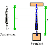
The forces exerted by the ends of the spring always act along the line of the spring. The magnitude of the force is (so long as you don’t stretch the spring too much) given by the formula
F = k(L - a)
where a is the un-stretched spring length; L is the stretched length, and k is the spring stiffness.
In the SI system, k has units of N/m.
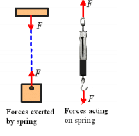
Note that when you draw a picture showing the forces exerted by a spring, you must always assume that the spring is stretched, so that the forces exerted by the spring are attractive. If you don’t do this, your sign convention will be inconsistent with the formula F = k(L - a), which assumes that a compressed spring (L<a) exerts a negative force.
Forces exerted by dashpots
A ‘Dashpot’ is somewhat like a spring except that it exerts forces that are proportional to the relative velocity of its two ends, instead of the relative displacement. The device is extremely useful for damping vibrations. The device usually consists of a plunger that forces air or fluid through a small orifice – the force required to expel the fluid is roughly proportional to the velocity of the plunger.
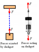
The forces exerted by the ends of the dashpot always act along the line of the dashpot. The magnitude of the force exerted by a fluid filled dashpot is given by the formula
F = 
where L is the length, and η is the rate constant of the dashpot. Air filled dashpots are somewhat more complicated, because the compressibility of the air makes them behave like a combination of a dashpot and spring connected end-to-end.
In the SI system, η has units of Ns/m.
Note that when you draw a picture showing the forces exerted by a dashpot, you must always assume that the length of the dashpot is increasing, so that the forces exerted by the ends of the dashpot are attractive.
Forces exerted by an ‘Inerter’
The ‘Inerter’ is a device that exerts forces proportional to the relative acceleration of its two ends. It was invented in 1997 and used in secret by the McLaren Formula 1 racing team to improve the performance of their cars, but in 2008 was made broadly available
The device is so simple that it is difficult to believe that it has taken over 100 years of vehicle design to think of it – but the secret is really in how to use the device to design suspensions than in the device itself. The device works by spinning a flywheel between two moving rods, as sketched in the figure.
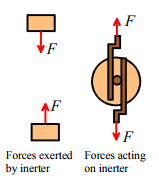
The forces exerted by the ends of the inerter always act along the line of the inerter. The magnitude of the force exerted by an inerter is given by the formula

where L is the length, and μ is the inertia constant of the dashpot.
In the SI system, μ has units of Ns2 /m.
Electrostatic Forces
As an engineer, you will need to be able to design structures and machines that manage forces. Controlling gravity is, alas, beyond the capabilities of today’s engineers. It’s also difficult (but not impossible) to design a spring with a variable stiffness or unstretched length. But there are forces that you can easily control. Electrostatic and electromagnetic forces are among the most important ones.
Electrostatic forces are exerted on, and by, charged objects. The concepts of electrical potential, current and charge are based on experiments. A detailed discussion of these topics is beyond the scope of this course (it will be covered in detail in EN51), but electromagnetic and electrostatic forces are so important in the design of engines and machines that the main rules governing forces in these systems will be summarized here.
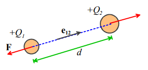
Electrostatic forces acting on two small charged objects that are a large distance apart
Coulomb’s Law states that if like charges Q1 and Q2 are induced on two particles that are a distance d apart, then particle 1 will experience a force
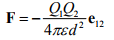
(acting away from particle 2), where ε is a fundamental physical constant known as the Permittivity of the medium surrounding the particles (like the Gravitational constant, its value must be determined by experiment).
In SI units, Q1,Q2, are specified in Coulombs, d is in meters, and ε is the permittivity of free space, with fundamental units Amperes2 kg-1 m-3. Permittivity is more usually specified using derived units, in Farads per meter. The Farad is the unit of capacitance.
The value of ε for air is very close to that of a vacuum. The permittivity of a vacuum is denoted by ε0 . In SI units its value is approximately 8.854185 × 10⁻¹² Fm-1
Like gravitational forces, the electrostatic forces acting on 3D objects with a general distribution of charge must be determined using complicated calculations. It’s worth giving results for two cases that arise frequently in engineering designs:
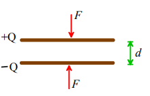
Forces acting between charged flat parallel plates
Two parallel plates, which have equal and opposite charges Q and are separated by a distance d , experience an attractive force with magnitude
F = Q2 /(2ε)
The force can be thought of as acting at the center of gravity of the plates.
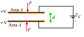
Two parallel plates, which have area A, are separated by a distance d, and are connected to a powersupply that imposes an electrical potential difference V across the plates, experience an attractive force with magnitude
F =AV2ε /(2d2)
The force can be thought of as acting at the center of gravity of the plates.
Applications of electrostatic forces:
Electrostatic forces are small, and don’t have many applications in conventional mechanical systems. However, they are often used to construct tiny motors for micro-electro-mechanical systems (MEMS). The basic idea is to construct a parallel-plate capacitor, and then to apply force to the machine by connecting the plates to a power-supply. The pictures below show examples of comb drive motors.
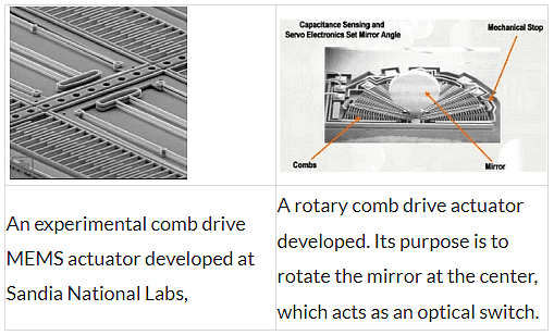 The configurations used in practice are basically large numbers of parallel plate capacitors. A detailed discussion of forces in these systems will be deferred to future courses.
Electrostatic forces are also exploited in the design of oscilloscopes, television monitors, and electron microscopes. These systems generate charged particles (electrons), for example by heating a tungsten wire. The electrons are emitted into a strong electrostatic field, and so are subjected to a large force. The force then causes the particles to accelerate – but we can’t talk about accelerations in this course so you’ll have to take EN4 to find out what happens next…
Electromagnetic Forces
Electromagnetic forces are exploited more widely than electrostatic forces, in the design of electric motors, generators, and electromagnets.
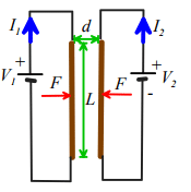
Ampere’s Law states that two long parallel wires which have length L, carry electric currents I1 and I2 , and are a small distance d apart, will experience an attractive force with magnitude
F = μ0I1 I2 L /(2πd)
where μ0 is a constant known as the permeability of free space.
In SI units, μ0 has fundamental units of kg m2 sec-1 A -2, but is usually specified in derived units of Henry per meter. The Henry is the unit of inductance
The value of μ0 is exactly 4π ×10-7 H/m
Electromagnetic forces between more generally shaped current carrying wires and magnets are governed by a complex set of equations. A full discussion of these physical laws is beyond the scope of this course, and will be covered in EN51.
Applications of electromagnetic forces
Electromagnetic forces are widely exploited in the design of electric motors; force actuators; solenoids; and electromagnets. All these applications are based upon the principle that a current-carrying wire in a magnetic field is subject to a force. The magnetic field can either be induced by a permanent magnet (as in a DC motor); or can be induced by passing a current through a second wire (used in some DC motors, and all AC motors). The general trends of forces in electric motors follow Ampere’s law: the force exerted by the motor increases linearly with electric current in the armature; increases roughly in proportion to the length of wire used to wind the armature, and depends on the geometry of the motor.
Two examples of DC motors – the picture on the right is cut open to show the windings.
|
24 videos|69 docs|53 tests
|
FAQs on Forces - Engineering Mechanics - Civil Engineering (CE)
| 1. What are the causes of force? |  |
| 2. How can forces be mathematically represented? | |
| 3. How are forces measured? | |
| 4. What are force laws? | |
| 5. What are electromagnetic forces? | |


practice quizzes
,Objective type Questions
,past year papers
,Forces | Engineering Mechanics - Civil Engineering (CE)
,study material
,Free
,Exam
,mock tests for examination
,Forces | Engineering Mechanics - Civil Engineering (CE)
,ppt
,Semester Notes
,Extra Questions
,Summary
,shortcuts and tricks
,Sample Paper
,Previous Year Questions with Solutions
,video lectures
,Important questions
,MCQs
,Forces | Engineering Mechanics - Civil Engineering (CE)
,Viva Questions
;


Forces Free PDF Download
Importance of Forces
Forces Notes
Forces Civil Engineering (CE) Questions
Study Forces on the App
|
© EduRev
|
Education Revolution
|


|


