
Best Study Material for Civil Engineering (CE) Exam
Civil Engineering (CE) Exam > Civil Engineering (CE) Notes > State Space Representation of MIMO System
State Space Representation of MIMO System - Civil Engineering (CE) PDF Download
Why State Space Control is Required
- Transform method of controller design is generally suitable for designing simple analog control circuits for SISO (Single input single output) system). Control of a realistic system may require many sensors and actuators and since all of them are related with a single system, their performances are coupled. Hence, design of multiple decoupled SISO controllers is not feasible in such cases.
- Moreover, transform method is difficult to implement for a MIMO system, since for m number of actuators and n number of sensors, one will have mn number of transfer functions and one has to design as many controllers for the system. With the advent of computers and computer based digital control, one can design control systems for the MIMO systems directly in the time domain. The governing equation of motion in such linear dynamic systems is represented as a set of first order differential or difference equations commonly known as state space representation of the system.
Formal Definion
Knowledge of the state variables defines the initial, current and future response of a system. An n - dimensional state-space is defined as the space generated by the smallest set of linearly independent variables x(t0 )…..xn (t0 ) at t=t0 ( n states of the system), which, together with the m number of given inputs u1 (t)….um (t) for t=t0 determine the states at any future time t>t0 . The standard form of state-space equations is expressed as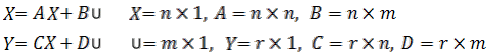 (24.1)
where, x represents the n -dimensional state vector, y the output vector, u the control input, A the system matrix, B the actuator influence matrix, C provides the sensor influence matrix and D the direct transmission matrix. Usually, D is considered as zero except for feed-forward systems. The example in the next slide shows how to obtain the state-space representation of a multiple degrees of freedom system
Example
Consider a two DOF vibrating system supported on friction-less wheels as shown in Fig. 24.1. Obtain the state space representation of the system.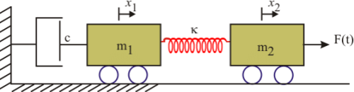
Figure 24.1: 2 DOF vibration system
Solution The equation of motion of the 2 DOF system may be written as: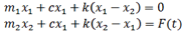 (24.2)
Consider the state vector x as: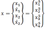
Eqn 24.2 could be expressed as a set of four first order ODEs with respect to the above state vector. The ODEs could be written as: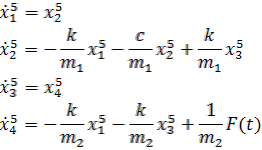 (24.3)
The output measured by the sensors may vary from case to case. For example, considering a case, where, velocity of the first mass  and the relative displacement between the two masses (x1– x2 ) are only measurable. The equations could be now expressed in matrix-form resembling Eqn. (24.1) as
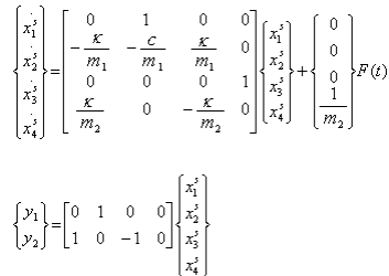
State-space systems representing a set of ODEs as the state equation could be solved using standard mathematical techniques. One simple form is discussed here for the sake of brevity. Pre-multiplying the state space equation 25.1 by the matrix e-At we get: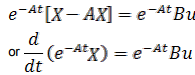
Integrating the above equation from 0 to time t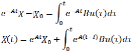 (24.5)
The matrix eAt is known as the state transition matrix since it transforms any initial state x (0) to states at any time t, and is denoted as  The state transition matrix is unique for each dynamic system and could be computed by inverse Laplace transformation of the matrix (s I - A) as
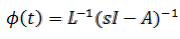 (24.6)
The eigen-values of the plant A could be obtained by finding out the roots of the polynomial equation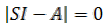 (24.7)
Eqn. (24.7) is also known as the characteristic equation of the open-loop system. The roots of the characteristic equation could be plotted in a real vs. imaginary-plane ( s -plane). For a stable open-loop system, these roots are always situated in the left side of the imaginary axis in the s -plane.
The Root Locus method
The root locus method is used to study the change in the pole-location of a closed-loop system in the s-plane with respect to the change in the control-gain. A simple closed loop system is described as follows: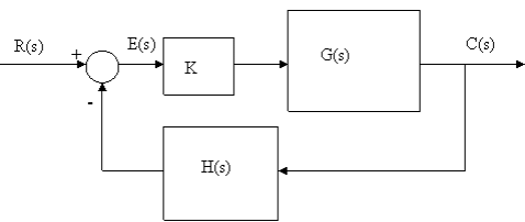
Figure 24.5
Following the block-diagram, the error E(s) is
E(s) = R(s) – H(s) C(s) (24.9)
Again
C(s) = K G(s) E(s) = K G(s) [R(s) – H(s) C(s)] (24.10)
Hence,
C(s)/R(s) = K G(s) /[1+K G(s) H(s)] (24.11)
Equation (24.11) is known as the closed-loop transfer function for a negative feed-back system. The characteristic equation corresponding to a unity feedback (H(s) =1) for the above system could be written as
1 + K G(s) = 0 (24.12)
The above equation could be expressed in terms of magnitude and phase as follows: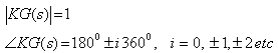 (24.13)
Using the phase relationship of the above equation, one can plot the locus of the roots of the characteristic equation as K varies from 0 to infinity.
The following are the basic rules used for plotting the root-locus corresponding to a transfer function having n open-loop poles and m open-loop zeros.
1. The n branches of root-locus start at the n open-loop poles and out of them m branches end at the m open-loop zeros, while the n-m branches end at infinity.
2. On the real axis, the root-loci exist on the left side of odd number of poles and zeros.
3. The root locus is symmetric about the real axis.
4. The asymptodes of root-locus at infinity have the following real-axis intercept s and angle θ:
where, P and Zs are finite poles and zeros already defined by Eqn.24.5.
5. The angle of arrival and departure from the poles and zeros are calculated by choosing a point very close to such desired poles and zeros. Now, using a simple graphical technique, vectors are drawn to the desired pole/zero from all the other poles and zeros. Adding the angles of the zeros and subtracting that of the poles the net angle is obtained at the point as θnet . Subtracting this angle from 1800 would yield the angle of departure/arrival of the root-locus.
6. The root-locus crosses the imaginary axis at the points where the angle of G(s)H(s) becomes equal to (2k+1)1800
The document State Space Representation of MIMO System - Civil Engineering (CE) is a part of Civil Engineering (CE) category.
All you need of Civil Engineering (CE) at this link: Civil Engineering (CE)


FAQs on State Space Representation of MIMO System - Civil Engineering (CE)
| 1. What is the state space representation of a MIMO system? |  |
| 2. How is the state space representation different from other representations of a MIMO system? | |
Ans. The state space representation is different from other representations, such as transfer function or block diagram, as it provides a more comprehensive and flexible representation of the system. It allows for the analysis of system dynamics, stability, and control design using techniques like eigenvalues and eigenvectors.
| 3. What are the advantages of using state space representation for a MIMO system? | |
Ans. The advantages of using state space representation for a MIMO system include:
- It provides a complete description of the system's behavior.
- It allows for the analysis of system stability, controllability, and observability.
- It enables the use of modern control design techniques, such as state feedback and observer design.
- It can handle systems with multiple inputs and multiple outputs, which is not easily achieved using other representations.
- It is suitable for both time-domain and frequency-domain analysis.
| 4. How can the state space representation be obtained for a MIMO system? | |
Ans. The state space representation for a MIMO system can be obtained through various methods, such as:
- Physical modeling: Deriving the state equations based on the physical laws governing the system.
- System identification: Estimating the state space model from input-output data using techniques like least squares or system identification algorithms.
- Transfer function to state space conversion: If the system's transfer function is known, it can be converted to a state space representation using methods like pole placement or diagonalization.
| 5. Can the state space representation handle time-varying systems in a MIMO system? | |
Ans. Yes, the state space representation can handle time-varying systems in a MIMO system. The state equations can be formulated to incorporate time-varying parameters or matrices, allowing for the modeling and analysis of dynamic systems with changing characteristics. Time-varying systems can be represented using time-varying state matrices or by adding additional states to capture the time-varying behavior.
Related Exams
About this Document

4.81/5
Rating

Apr 07, 2025
Last updated
Document Description: State Space Representation of MIMO System for Civil Engineering (CE) 2025 is part of Civil Engineering (CE) preparation. The notes and questions for State Space Representation of MIMO System have been prepared according to the Civil Engineering (CE) exam syllabus. Information about State Space Representation of MIMO System covers topics like and State Space Representation of MIMO System Example, for Civil Engineering (CE) 2025 Exam. Find important definitions, questions, notes, meanings, examples, exercises and tests below for State Space Representation of MIMO System.
Introduction of State Space Representation of MIMO System in English is available as part of
our Civil Engineering (CE) preparation & State Space Representation of MIMO System in Hindi for Civil Engineering (CE)
courses. Download more important topics, notes, lectures and mock test series for Civil Engineering (CE)
Exam by signing up for free. Civil Engineering (CE): State Space Representation of MIMO System - Civil Engineering (CE)
Description
Full syllabus notes, lecture & questions for State Space Representation of MIMO System - Civil Engineering (CE) - Civil Engineering (CE) | Plus excerises question with solution to help you revise complete syllabus | Best notes, free PDF download
Information about State Space Representation of MIMO System
In this doc you can find the meaning of State Space Representation of MIMO System defined & explained in the simplest way possible.
Besides explaining types of State Space Representation of MIMO System theory,
EduRev gives you an ample number of questions to practice State Space Representation of MIMO System tests, examples and also practice Civil Engineering (CE) tests.
Download as PDF
Top Courses for Civil Engineering (CE)

Related Searches
Extra Questions
,ppt
,Free
,State Space Representation of MIMO System - Civil Engineering (CE)
,Exam
,Objective type Questions
,shortcuts and tricks
,Viva Questions
,State Space Representation of MIMO System - Civil Engineering (CE)
,State Space Representation of MIMO System - Civil Engineering (CE)
,study material
,Summary
,past year papers
,video lectures
,Sample Paper
,practice quizzes
,Semester Notes
,Important questions
,mock tests for examination
,Previous Year Questions with Solutions
,MCQs
;


Additional Information about State Space Representation of MIMO System for Civil Engineering (CE) Preparation
State Space Representation of MIMO System Free PDF Download
The State Space Representation of MIMO System is an invaluable resource that delves deep into the core of the Civil Engineering (CE) exam.
These study notes are curated by experts and cover all the essential topics and concepts, making your preparation more efficient and effective.
With the help of these notes, you can grasp complex subjects quickly, revise important points easily,
and reinforce your understanding of key concepts. The study notes are presented in a concise and easy-to-understand manner,
allowing you to optimize your learning process. Whether you're looking for best-recommended books, sample papers, study material,
or toppers' notes, this PDF has got you covered. Download the State Space Representation of MIMO System now and kickstart your journey towards success in the Civil Engineering (CE) exam.
Importance of State Space Representation of MIMO System
The importance of State Space Representation of MIMO System cannot be overstated, especially for Civil Engineering (CE) aspirants.
This document holds the key to success in the Civil Engineering (CE) exam.
It offers a detailed understanding of the concept, providing invaluable insights into the topic.
By knowing the concepts well in advance, students can plan their preparation effectively.
Utilize this indispensable guide for a well-rounded preparation and achieve your desired results.
State Space Representation of MIMO System Notes
State Space Representation of MIMO System Notes offer in-depth insights into the specific topic to help you master it with ease.
This comprehensive document covers all aspects related to State Space Representation of MIMO System.
It includes detailed information about the exam syllabus, recommended books, and study materials for a well-rounded preparation.
Practice papers and question papers enable you to assess your progress effectively.
Additionally, the paper analysis provides valuable tips for tackling the exam strategically.
Access to Toppers' notes gives you an edge in understanding complex concepts.
Whether you're a beginner or aiming for advanced proficiency, State Space Representation of MIMO System Notes on EduRev are your ultimate resource for success.
State Space Representation of MIMO System Civil Engineering (CE) Questions
The "State Space Representation of MIMO System Civil Engineering (CE) Questions" guide is a valuable resource for all aspiring students preparing for the
Civil Engineering (CE) exam. It focuses on providing a wide range of practice questions to help students gauge
their understanding of the exam topics. These questions cover the entire syllabus, ensuring comprehensive preparation.
The guide includes previous years' question papers for students to familiarize themselves with the exam's format and difficulty level.
Additionally, it offers subject-specific question banks, allowing students to focus on weak areas and improve their performance.
Study State Space Representation of MIMO System on the App
Students of Civil Engineering (CE) can study State Space Representation of MIMO System alongwith tests & analysis from the EduRev app,
which will help them while preparing for their exam. Apart from the State Space Representation of MIMO System,
students can also utilize the EduRev App for other study materials such as previous year question papers, syllabus, important questions, etc.
The EduRev App will make your learning easier as you can access it from anywhere you want.
The content of State Space Representation of MIMO System is prepared as per the latest Civil Engineering (CE) syllabus.
|
© EduRev
|
Education Revolution
|


|


Signup to see your scores
go up within 7 days!
Access 1000+ FREE Docs, Videos and Tests
Takes less than 10 seconds to signup