Conveyance Structures for Canal Flows (Part - 1) - Civil Engineering (CE) PDF Download

Introduction
A canal conveying water from the head works has to run for large distances and has to maintain the water levels appropriately, as designed along its length. It has to run through terrains which generally would have a different slope small than the canal . The surrounding areas would invariably have its own drainage system ranging from small streams to large rivers . The canal has to carry the water across these water bodies as well as across artificial obstacles like railway line or roads .
The main structures of a canal system for conveyance of canal flow and control of water levels are as follows .
- Pipe conduits, culverts and inverted syphons to carry flow under railways and highways .
- Aqueducts, syphon aqueducts, super-passage, canal siphon or level crossings across natural drainage courses or other depressions.
- Transitions at changes in cross sections.
This lesson deals with the concepts of planning, layout and design of canal structures for flow conveyance across artificial and natural obstacles.
Structures for crossing canals across roads and railway lines
These are structural elements to convey canal water under roads or railway lines. For small roads, carrying relatively less traffic, the pipe conduit is sufficient. A general view of the pipe conduit is shown in Figure 1 and its typical plan and cross section in Figure 2. For canals crossing under major highways and railway tracks, reinforced concrete culverts are more commonly adopted. These roads or railway crossings are usually having a straight profile along its length. The water level in the canal for this type of crossing is lower than the level of the obstruction it crosses, as may be noticed from Figure 2 and the flow through the pipe may be free or under mild pressure.
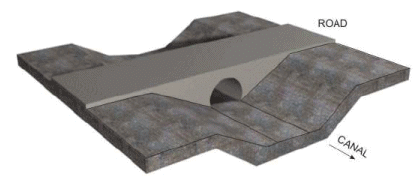
FIGURE 1. Pipe conduits for canals crossing small roads
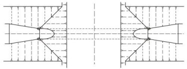
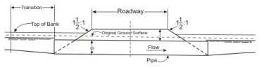
FIGURE 2. Plan and section of road crossing with pipe conduit
Pipe road crossings are relatively economical, easily designed and built, and have proven a reliable means of conveying water under a roadway. Pipe installations are normally installed by cut and cover method below minor roads but for important roads, where traffic cannot be interrupted, it may be accomplished by jacking the pipe through the roadway foundation.
The inverted syphons are structures for canal water conveyance below roads, railway lines and other structures (Figure 3). The longitudinal profile is not exactly in a straight line and the central portion is seen to sag beneath the object to be crossed. The inverted syphon, therefore, is provided where the water level in the canal is about the same as the level of the obstruction (Figure 4).
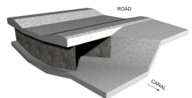
FIGURE 3. Inverted Syphon below roads showing rectangular section. Circular section also possible
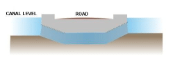
FIGURE 4a. Canal Full Supply Level(FSL) and road level are nearly same
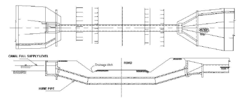
FIGURE 4b. An example of an inverted syphon of a small canal crossing a road
The inverted syphon is a closed conduit designed to run full and under pressure . If made of pressure pipes , they should be able to withstand the load of cover and wheel from outside and the hydrostatic head from inside . Transitions for changes in cross sections are nearly always used at inlet and outlet of a siphon to reduce head losses and prevent erosion in unlined canals caused by the velocity changes between the canal and the pipe.
Structures for crossing canals across natural streams (cross drainage works)
These structural elements are required for conveying the canals across natural drainage. When a canal layout is planned, it is usually seen to cross a number of channels draining the area, varying from small and shallow depressions to large rivers. It is not generally possible to construct cross-drainage structures for each of the small streams. Some of the small drainage courses are, therefore, diverted into one big channel and allowed to cross the canal. However, for larger streams and river, where the cost of diversion becomes costlier than providing a separate cross-drainage work, individual structures to cross the canal across the stream is provided.
There could be a variety of combinations of the relative position of the canal with respect the natural channel that is to be crossed. These conditions are shown in Figures 5 to 9. The notations used in the figures are as follows:
(a) CBL: Canal Bed Level;
(b) SBL: Stream Bed Level;
(c) FSL: Canal Full Supply Level; and
(d) HFL: Stream High Flood Level
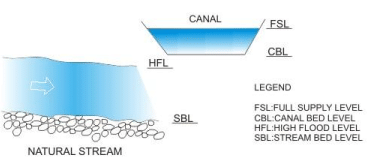
FIGURE 5. Relative position of canal (shown in cross section) with respect to a natural stream (shown in longitudinal section), when canal bed level is higher than stream high flood level
Figure 5 shows the relative position of canal (shown in cross-section) with respect to a natural stream (shown in longitudinal section), when canal bed level is higher than stream high flood level.
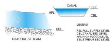
FIGURE 6 . Relative position of a canal whose canal bed level is below the high flood of the stream.
Figure 6 shows the relative position of a canal whose bed level is below but full supply level is above the stream high flood level.
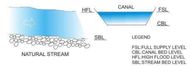
FIGURE 7 . Canal with full supply level almost matching the high flood level of the natural stream
Figure 7 shows a canal with full supply level almost matching the high flood level of the natural stream.
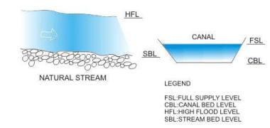
FIGURE 8 . Canal full supply level and bed levels below the levels of high Hood level and bed level of the stream, respectively.
Figure 8 shows a canal full supply level and bed levels below the levels of high flood level and bed level of stream, respectively.

FIGURE 9 . Relation position of canal with respect to the natural stream where the canal full supply level is below the stream bed level
Figure 9 shows the relative position of canal with respect to the natural stream where the canal full supply level is below the stream bed level.
In general , the solution for all the illustrated conditions possible for conveying an irrigation canal across a natural channel is by providing a water conveying structure which may:
(a) Carry the canal over the natural stream;
(b) Carry the canal beneath the natural stream; or
(c) Carry the canal at the same level of the natural stream.
FAQs on Conveyance Structures for Canal Flows (Part - 1) - Civil Engineering (CE)
| 1. What are conveyance structures for canal flows? |  |
| 2. Why are conveyance structures important in canal systems? | |
| 3. What are the different types of conveyance structures used in canal flows? | |
| 4. How do conveyance structures help in the maintenance of canal flows? | |
| 5. What factors should be considered when designing conveyance structures for canal flows? | |


Conveyance Structures for Canal Flows (Part - 1) - Civil Engineering (CE)
,Extra Questions
,mock tests for examination
,practice quizzes
,MCQs
,Sample Paper
,Important questions
,Summary
,Conveyance Structures for Canal Flows (Part - 1) - Civil Engineering (CE)
,study material
,Exam
,video lectures
,shortcuts and tricks
,Viva Questions
,Conveyance Structures for Canal Flows (Part - 1) - Civil Engineering (CE)
,Objective type Questions
,past year papers
,ppt
,Semester Notes
,Free
,Previous Year Questions with Solutions
;


Conveyance Structures for Canal Flows (Part - 1) Free PDF Download
Importance of Conveyance Structures for Canal Flows (Part - 1)
Conveyance Structures for Canal Flows (Part - 1) Notes
Conveyance Structures for Canal Flows (Part - 1) Civil Engineering (CE) Questions
Study Conveyance Structures for Canal Flows (Part - 1) on the App
|
© EduRev
|
Education Revolution
|


|


