Structures for Flow Diversion, Investigation Planning and Layout (Part - 4) - Civil Engineering (CE) PDF Download

River training works
The river training works for barrages are required to achieve the following;
- Prevent out flanking of the structure
- Minimize cross flows through the barrage
- prevent flooding by the river lands upstream
- provide favourable curvature of flow at the head regulator from the point of sediment entry into the canal, and
- guide the river to flow axially through the barrage or weir
As was seen in the section on waterway, it is necessary at many instances to narrow down and restrict the course of the river through the barrage and it is achieved by the use of the river training works. Proper alignment of guide bunds is essential to ensure satisfactory flow conditions in the vicinity of the barrage. In case of wide alluvial banks, the length and curvature at the head of the guide bunds should be kept such that the worst meander loop is kept away from either the canal embankment or the approach embankment. If the alluvial bank is close to the barrage, the guide bunds may be connected to it by providing suitable curvature, if necessary. If there is any out-crop of hard strata on the banks, it is advisable to tie the guide bunds to such control points. Two typical guide bund layouts are shown in Figure 11.
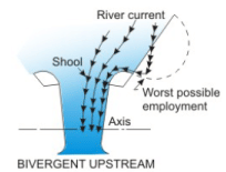


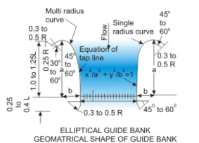

Figure 11. Typical layouts of guide banks
The dimensions given in Figure 11 are preliminary, and model studies have to be carried out for fixation of final sizes for any particular project depending upon the prevalent site conditions.
Crest levels of spillway and undersluice bays
The bays of a barrage are in the shape of weirs or spillways and the crest levels of these have to be decided correctly. Some of the bays towards the canal end of the barrage are provided with lower crest (Figure 12) in order to:
- Maintain a clear and well defined river channel towards the canal head regulator
- To enable the canal to draw silt free water from surface only as much as possible
- To scour the silt deposited in front of the head regulator

Figure 12. Relative shapes of under sluice bays (towards the canal end) and spillway bays of a barrage. Piers, gates and walls have not been shown.
The set of undersluice bays withlow crest elevations are separated from the set of spillway bays witha small weir hump by a long wall, called the divide wall.
The layout of a barrage and its appurtenant structures can be seen from a typical plan view shown in Figure 13. The important components of a barrage are discussed below:

FIGURE 13. A typical layout of a barrage and its appurtenant structure. This example shows canal off-taking from either end
Spillway bays
This is the main body of the barrage for controlling the discharges and to raise the water level to the desired value to feed the canals. It is a reinforced concrete structure designed as a raft foundation supporting the weight of the gates, piers and the bridge above to prevent sinking into the sandy river bed foundation. A typical section of a spillway bay is shown in Figure 14.

FIGURE 14. Typical section of spillway of a barrage
Undersluice bays
These low crested bays may be provided on only one flank or on bothflanks of the river depending upon whether canals are taking-off from one or both sides. The width of the undersluice portion is determined on the basis of the following considerations.
- It should be capable of passing at least double the canal discharge to ensure good scouring capacity
- It should be capable of passing about 10 to 20 percent of the maximum flood discharge at high floods
- It should be wide enough to keep the approach velocities sufficiently lower than critical velocities to ensure maximum settling of suspended silt load.
Undersluices are often integrated withRCC tunnels or barrels, called silt excluders, extending up to the widthof the Canal Head Regulator, as can be seen from Figure 13. These tunnels are provided in order to carry the heavier silt from a distance upstream and discharge it on the downstream, allowing relatively clear water to flow above from which the Canal Head Regulator draw its share of water.
Typical sections of undersluices with and without silt excluder tunnel are shown in Figures 15 and 16.

FIGURE 15. Typical section of uridersluice wilii silt excluder tunnels

River –sluice bays
River sluices are a set of sluices similar to the undersluices located in between the undersluice and spiilway bays and separated from them by means of divide walls. These are generally provided in long barrages (that is, in wide rivers) for simplifying the operation of gates during normal floods and to have better control on the river. The section of river-sluice bays would generally be similar to that of undersliuce bays without silt excluding tunnels.
Cut-off
Cut-offs are barriers provided below the floor of the barrage both at the upstream and the downstream ends. They may be in the form of concrete lungs or steel sheet-piles, as observed from the figures 14, 15 and 16. The cut-offs extend from one end of the barrage up to the other end (on the other bank). The purpose of providing cutoff is twofolds as explained below.
During low-flow periods in rivers, when most of the gates are closed in order to maintain a pond level, the differential pressure head between upstream and downstream may cause uplift of river bed particles (Figure 17a). A cutoff increases the flow path and reduces the uplift pressure, ensuring stability to the structure (Figure 17b).

Figure 17. Downstream riverbed uplift and its prevention. (A) Differential pressure head causing sand uplift; (B) Cutoffs to reduce uplift pressure by increasing the seepage path.
During flood flows or some unnatural flow condition, when there is substantial scour of the downstream riverbed, the cutoffs or sheet piles protect the undermining of the structures foundation (Figure 18).

Figure 18. Riverbed scour resisted by sheet pile protects the foundation barrage floor.
Pier
Piers are provided between each bay. The gates operate through the groove provided in the piers. Usually, there are two sets of grooves, the upstream being called the Stop Log groove and the downstream one being called the Main Gate or Service gate groove. The piers are constructed usually monolithic with the floor (raft), and extend usually from the upstream end to the downstream end solid floor of the spillway (or under sluice/river sluices), as may be observed from Figure 2B. The piers have to be high enough to hold the gates clear off the maximum flood level while making ample allowance for passing any floating debris under the raised gates.
Divide wall
The divide wall is much like a pier and is provided between the sets of undersluice or river sluice or spill bays. The main functions of a divide wall:
- It separates the turbulent flood waters from the pocket in front of the canal head.
- It helps in checking parallel flow (to the axis of the barrage) which would be caused by the formation of deep channels leading from the river to the pocket in front of the sluices.
The length of the divide wall on the upstream has to be such as to keep the heavy action on the nose of the divide wall away from the upstream protection of the sluices and also to provide a deep still water pond in front of the canal head regulator.
A typical section of a divide wall is shown in Figure 19.

figure 19. Typical section through a divide wall
Abutment
The abutments form the end structures of the barrage and their layout depends upon the project features and topography of the site. The lengthof the abutment is generally kept same as the lengthof the floor. The top of the abutment is fixed withadequate free board over the upstream and downstream water levels.
Flank wall
In continuation of the abutments of the diversion structure, flank walls are provided bothon the upstream and downstream sides on boththe banks. The flank walls ensure smoothentry and exit of water and away from the diversion structure. The flank walls laid out in a flare withvertical alignment close to the abutment and a slope of 2H:1V or 3H:1V on the other end, as may be observed from the layout of the barrage shown in Figure 13.
Return wall
Return walls are generally provided at right angles to the abutment either at its end or at the flank wall portion, and extends into the banks to hold the bank or back-filling earth in place.
Guide bunds
The requirement of narrowing down and restricting wide alluvial river courses to flow axially through the barrage necessitates the use of guide bunds, as shown in Figure 10.
Afflux bunds
Afflux bunds are components of the diversion structures wherever necessary to protect important low lying properties adjacent to the structures from submergence due to affluxed high floods.
Silt excluding devices
As shown in the layout of a barrage (Figure 13), the silt excluding tunnels carry heavy silt down the river below the undersluices.
Navigation Lock
Since inland or river water navigation is economically more attractive for larger cargo, navigation facilities can be combined withthe barrage projects. This includes the provision of a navigation channel withnavigation locks suitably incorporated to allow passage of crafts to move from upstream to downstream and vice versa (Figure 4).
Fish pass
Some barrages require providing special structures to allow migratory fishes to flow up and down the river through structures called Fish Passes or Fish Locks (Figure 5).
Canal Head Regulator
The water that enters a canal is regulated through a Head Regulator. A typical cross section through a regulator is shown in Figure 9. As it is desirable to exclude silt as much as possible from the head regulator, the axis of the head regulator is laid out at an angle from 900 to 1100 to the barrage axis as recommended in Bureau of Indian Standards code IS : 6531(1972) “Criteria for design of canal head regulators”. A typical layout of a head regulator is shown in Figure 20.

FIGURE 20. Typical layout of a canal head regulator
Finalisation of barrage layout through model studies
It may be realised that a being a structure spanning across a river, may cause enormous changes to the river hydraulics and morphology. Much of this is dynamic, since the floods every year would generally be of different magnitude or duration and accordingly the gate operation would be different each time. Hence the planning and layout decided from the general principles discussed earlier in this lesson may only be taken as a guideline. The final position, location, layout, alignment of each component of the structure and in relation to each other has to be done through model studies. The Bureau of Indian Standard code IS 14955: 2001 “Guidelines for hydraulic model studies of barrages and weirs” lays down the basic principles of model studies and could be followed to finalise the layout of a particular barrage project.
FAQs on Structures for Flow Diversion, Investigation Planning and Layout (Part - 4) - Civil Engineering (CE)
| 1. What is flow diversion in civil engineering? |  |
| 2. How is investigation planning important in civil engineering projects? | |
| 3. What are the key elements to consider in the layout design of civil engineering projects? | |
| 4. How can flow diversion structures be used to prevent flooding? | |
| 5. What are the benefits of proper investigation planning in civil engineering projects? | |


Top Courses for Civil Engineering (CE)

Previous Year Questions with Solutions
,Structures for Flow Diversion
,Investigation Planning and Layout (Part - 4) - Civil Engineering (CE)
,Investigation Planning and Layout (Part - 4) - Civil Engineering (CE)
,Structures for Flow Diversion
,Investigation Planning and Layout (Part - 4) - Civil Engineering (CE)
,ppt
,practice quizzes
,video lectures
,Free
,Important questions
,Semester Notes
,Sample Paper
,Objective type Questions
,Extra Questions
,shortcuts and tricks
,Viva Questions
,Exam
,study material
,Structures for Flow Diversion
,MCQs
,past year papers
,Summary
,mock tests for examination
;


Structures for Flow Diversion, Investigation Planning and Layout (Part - 4) Free PDF Download
Importance of Structures for Flow Diversion, Investigation Planning and Layout (Part - 4)
Structures for Flow Diversion, Investigation Planning and Layout (Part - 4) Notes
Structures for Flow Diversion, Investigation Planning and Layout (Part - 4) Civil Engineering (CE) Questions
Study Structures for Flow Diversion, Investigation Planning and Layout (Part - 4) on the App
|
© EduRev
|
Education Revolution
|


|


