Design and Construction of Concrete Gravity Dams (Part - 6) - Civil Engineering (CE) PDF Download

Temperature control of mass concrete for dams
When a concrete gravity dam is constructed of mass concrete, it undergoes volumetric changes with time due to the release of heat of hydration by the concrete. A rapid rise in the temperature of mass concrete takes place during the phase when the concrete mass is in plastic stage and undergoes hardening. After hardening, the concrete gradually cools due to effect of atmospheric temperature, which tends to subject the concrete to high tensile stresses. Cracking occurs in the concrete when these tensile stresses exceed the tensile strength of the concrete. This cracking is undesirable as it affects the water tightness, durability and appearance of hydraulic structures. Hence, methods to control the temperature rise during dam construction is absolutely essential. The methods to control temperature in dams is prescribed in the Bureau of Indian Standard code IS: 14591-1999 “Temperature control of mass concrete for dams – guidelines”, some of which are given below.
Most commonly used methods are precooking, post cooling and reducing heat of hydration by proper mix design. The ideal condition would be simply to place the concrete at stable temperature of dam and heat of hydration removed, as it is generated, so that temperature of concrete is not allowed to rise above stable temperature. However this is not possible to achieve practically. Therefore, the most practical method is to pre cool concrete so as to restrain the net temperature rise to acceptable levels.
Pre-cooling
One of the most effective and positive temperature control measure is precooling which reduces the placement temperature of concrete. The method, or combination of methods, used to reduce concrete placement temperatures will vary with the degree of cooling required and the equipment available with the project authority or the contractor. In this method usually the fine and coarse aggregates and the water are separately cooled to the requisite temperatures.
Mixing water may be cooled to varying degrees, usually from 00 C to 40 C. Adding crushed ice or ice flakes to the mix is an effective method of cooling because it takes advantage of the latent heat of fusion of ice. The addition of large amount of ice flakes, however, may not be possible in cases where both coarse aggregate and sand contain appreciable amount of free water, in which case the amount of water to be added to the mix may be so small that substitution of part of the water to be added with ice may not be feasible. From practical considerations, not more than 70 percent of water should be replaced by crushed ice. Although most rock minerals have comparatively low heat capacity, since aggregates comprise the greatest proportion of concrete mix, the temperature of the aggregate has the greatest influence on the temperature of the concrete. Cooling of coarse aggregate to about 1.7°C may be accomplished in several ways. One method is to chill the aggregates in large tanks of refrigerated water for a given period of time or by spraying cold water. Effective cooling of coarse aggregate is also attained by forcing refrigerated air through the aggregate while the aggregate is draining in stock piles, or while it is in a conveyer belt or while it is passing through the bins of the batching plant.
Post-cooling
Post cooling is a means of crack control. Control of concrete temperature may be effectively accomplished by circulating cold water through thin walled pipes embedded in concrete. This will reduce the temperature of newly placed concrete by several degrees, but the primary purpose of the system is to accelerate the subsequent heat removal and accompanying volume decrease, during early ages when the elastic modulus is relatively low. Post cooling is also used where longitudinal contraction joints are provided in order to reduce the temperature of concrete to the desired value prior to grouting of transverse contraction joint. Post cooling will create a flatter temperature gradient between the warm concrete and the cooler exterior atmosphere which, in turn, helps in avoiding temperature cracks. Other methods such as evaporative cooling with a fine water spray, cold water curing and shading may prove beneficial, but the results are variable and do not significantly affect the temperature in the interior of massive placement.
The embedded cooling system consist of aluminum or synthetic plastic pipe or tubing generally of 25 mm diameter and 1.50 mm wall thickness placed in grid like coils over the top of each concrete lift. When the expected active cooling period exceeds 3 months, steel tubing should be used. The number of coils in a block depends upon the size of the block and the horizontal spacing of the pipes. For practical reasons, pipe coils are placed and tied to the top of a hardened concrete surface and thus vertical spacing of the pipe corresponds to lift thickness. A horizontal spacing same as the vertical spacing will result in the most uniform cooling pattern but variations may be allowed. Supply and return headers, with manifolds to permit individual connections to each coil are normally placed on the downstream face of the dam. In some case, cooling shafts, galleries and embedded header system may be used to advantage.
Concreting procedures for gravity dams
A concrete gravity dam is normally executed as a mass concrete work, except for some reinforced concreting works as in:
- Piers and bridges over the spillway
- Around galleries and other openings
- Divide wall between adjacent spillways
- Energy dissipators
- Intake to sluices
- Power house if built as a part of the dam
The Bureau of Indian Standards code IS 457-1957 “Code of practice for general construction of plain and reinforced concrete for dams and other massive structures” provides guidelines for practices to be followed in plane and reinforced concreting for mass concrete dams. The main points that have to be taken care are mentioned in the following paragraphs
Aggregate production
Huge quantities of aggregate would be required for the construction of a massive structure like a concrete gravity dam The acceptability of the natural aggregate is to be judged upon the physical and the chemical properties of the material and the accessibility, proximity to site and economic workability of the deposit. A suitable quarry has to be identified in the neighbourhood that can supply continuous source of aggregates.
Structural steel
These may be according to the latest recommendations of the relevant bureau of Indian Standard Codes.
Concrete production and handling
Standard practice is for materials to be batched by weight. The time of mixing is often specified as 2 minutes. The procedure to be adopted for moving concrete from the mixers on to the dam will be governed by site conditions. Having produced a good plaeable concrete, the problem is to transport it to the dam site with the least possible segregation or change in consistency, so that it may be compacted uniformly into the dam without reasonable effort. Nowadays a cableway laid across the dam valley is often used with buckets of capacity 1.5 to 2 m³. At many construction sites concrete is placed using chutes or even a belt conveyor. It is recommended that concrete shall have to be placed in position within 30 minutes of its removal from the mixer.
Concrete placing, consolidation and curing
For laying concrete over the rock foundations, it has to be ensured that the surface is clean and free from mud, dirt, oil, organic deposits, or other foreign material which may prevent a tight bond between rock and concrete. In case of earth or shale foundations all soft or loose mud and surface debris shall have to be scrapped and removed. Then the surface has to be moistened to a depth of about 15 cm to prevent the subgrade from absorbing water from the fresh concrete. A layer of concrete that is laid is generally kept as 1.5 m, in a view to ease construction and limit excessive temperature rise. These layers of concreting are called lifts and between two successive lifts a horizontal joint would invariably arise. The concrete of subsequent lifts has to be placed after allowing sufficient time for the previously laid concrete to cool and attain its initial set and become hard. Prior to placement of concrete of the next lift, the surface of the previously placed concrete has to be thoroughly cleaned by the use of high velocity jet of water and air as well as by wet-sand blasting.
Further immediately before the concrete placing of the next lift begins, a 12.5 mm thick layer of mortar should be applied to permit proper bond between the concrete of the lower lift. Since the area of the concrete block near the foundation would be quite large, joints in the vertical plane, but parallel to the dam axis have to be introduced to ease the concrete placement and to allow safe dissipation of the heat of hydration of concrete. These joints called the longitudinal joints are normally spaced at intervals of 15m to 30 m. Thus during construction a continuous concrete pour is seen to be confined between the transverse joints (defining a block) and the longitudinal joints. Once a lift is cast it is thoroughly compacted with needle vibrators.
The longitudinal joints subdivide each block formed by the transverse joints into several smaller sub blocks, but since each block must be a monolithic, these joints are invariantly provided with horizontal keys (or undulations)over the entire surface, which helps to make a good bond with the adjacent lift . It has however, been recognized that the provision of longitudinal joints is basically unsound unless a high degree of perfection is maintained while placing the adjacent pore of concrete and then grouting the gap properly. Hence the present practice is to avoid the longitudinal joints altogether, even in the case of high dams and a better alternative is to attain necessary temperature control by the methods described earlier. Curing of concrete is important but a difficult task for the construction engineer. Primarily it is necessary to maintain satisfactory moisture content in the hardening concrete. This may be achieved either by the application of water (usually from sprinklers or perforated hoses, or occasionally by panding on the top of the lift) or by prevention of loss of water (by application of some membrane to the surface). A second requirement for good curing is favourable temperature. This can be achieved by any of the water methods but not by the membrane methods.
Instrumentation in concrete gravity dams
Normally, instruments are installed in a concrete gravity dam to measure the various parameters that indicate the structural health of the dam and the state of the foundation. These instruments have been classified into two types: obligatory and optional, by the Bureau of Indian Standards code IS 7436(part2)-1997 “Guide for types of measurements for structure in river valley projects and criteria for choice and location of measuring instruments”. These two types of instruments are explained in the following paragraphs.
Obligatory Measurements
The following measurements are obligatory for all dams:
- Uplift pressure at the base of the dam at a sufficient number of transverse sections
- Seepage into the dam and appearing downstream there-from;
- Temperature of the interior of the dam; and
- Displacement measurements - Except for very small structures (of height 20 m and below not involving any foundation complications). Displacement measurements should include one or more of the following types of -measurements:
- Those determined by suspended plumb lines;
- Those determined by geodetic measurements where warranted by the importance of the structure;
- Those determined by embedded resistance jointmeters at contraction joints where grouting is required to be done.
Optional Measurements
The following measurements are optional and may be undertaken where warranted by special circumstances of project. These would be beneficial for high dams, for structures of unusual design, for structures where unusual or doubtful foundations exist, for the verification of design criteria and for effecting improvement in future designs: a) Stress b) Strain c) Pore pressure (as distinct from uplift pressure), and d) Seismicity of the area and dynamic characteristic of the structure. Due to ever increasing demand of power, emphasis has been laid to construct large size of hydro electric project with very high dam. With the present trend, dam sites are neither geologically seismically suitable as most of the best sites have already been considered for the purpose.
Due to this reason those measurements that were considered optional at the time of framing this code may become obligatory now for high dams specially in the Himalayan region. The various types of parameters that are measured, whether obligatory or optional, are described in the following paragraphs.
Measurement of Uplift Pressure
It is important to determine the magnitude of any hydraulic pressure at the base of a dam. The effect of uplift on a dam is to reduce its effective weight on account of resulting buoyancy.
Measurement of Seepage
Seepage is, undoubtedly, the best indicator of the overall performance of a dam because this reflects the performance of entire dam and not just the condition at discrete instrumented points. Any sudden change in the quantity of seepage without apparent cause, such as a corresponding change in the reservoir level or a heavy rainfall, could indicate a seepage problem. Similarly, when the seepage water becomes cloudy or discoloured, contains increased quantities of sediment, or changes radically in chemical content, a likely serious seepage problem is indicated.
It is customary to provide grout curtain near the upstream face of the dam. Besides, a drainage curtain in the foundation and porous drain in the body of the dam are provided to intercept any seepage that passes through the grout curtain and through the body of the dam respectively. Measurement of seepage water along with uplift measurement at the plane of contact of the dam and its foundation will give direct indication of the effectiveness of the grout curtain and drainage curtain and will indicate whether any remedial measures are necessary. The chemical analysis of the seepage water through the foundation drainage system will help in assessing whether any foundation material is being washed out.
Likewise the quantum of water passing through ungrouted contraction joints or cracks would indicate about the workmanship in general as also any damage that might have been caused to the seals in the contraction joints. The chemical analysis of the water in the case of masonry dam may be indicative of any possible leaching action on the mortar used in the construction of the masonry dam. Corrective measures such as grouting of dam and foundation, besides improving existing drainage or providing additional drainage could thus be planned.
Wet spots or seepage appearing at new or unplanned locations at the abutments or downstream of a dam could also indicate a seepage problem. Measurement of-seepage downstream of the grout curtain provides a direct indication of the adequacy and effectiveness of the grout curtain, drainage curtain and functioning of the drains and holes to decide when and where remedial measures may be required.
Measurement of Temperature during Construction
For concrete gravity dams it is very important to know the thermic variations in the dam during its construction which enables to determine whether the concrete setting process is normal or otherwise. To achieve this purpose, temperature measuring devices are embedded within the dam body and also mounted on the surface according to a predetermined plan for useful observations. Any abnormal setting process indicated by temperature observations may lead to a change in the concrete lift height, and also changes in the treatment of aggregates before concreting and of the mass concrete during curing.
Measurement of Temperature of the Dam interior
It is necessary to measure temperature in the body of concrete and masonry dams in order to ascertain the nature and extent of thermal stresses and the consequent structural behaviour of the dam and also to ascertain when to undertake grouting of contraction joints that may have been provided for the structure.
Measurement of Temperature of Reservoir Water and Air
Measurement of temperature of reservoir water and air is essential for distinguishing the effects of ambient and water temperatures on such measurements as deflection, stresses, strains, joint movements and settlements.
Measurement of Displacement
Measurement of displacement of points either between two monoliths, or between foundation and body of the dam or the displacement of any joint of the dam with respect to the surrounding area will immediately reveal any distress conditions developing in the dam. Measurement of displacement is thus one of the most important factors to be studied while observing the structural behaviour of a dam.
Internal Joint Movement
Concrete and masonry dams are generally built in blocks separated by transverse joints. It is essential to know whether there is any relative movement between two blocks. The movement is likely to be due to differential foundation behaviour. Further, the relative movement of blocks is important from the point of view of growing of transverse contraction joints.
Surface Joint Movement
Measurement of joint movement at the surface of the locations accessible from galleries is made by detachable gauges with a view to assess the amount of joint opening of two blocks of the dam. These gauges may also be advantageously used for observation of opening or of closing of surface cracks at any location.
Foundation displacement
Measurement of vertical or horizontal displacement of foundation provides information for taking preventive measures for inclination, distortion etc. of structures. The data can also be used for studying the elastic and inelastic properties of dam and foundation. Measurement of foundation displacement involves vertical and horizontal displacement of part of foundation with respect to dam.
Displacement of One Part of the Dam Relative to other Parts of the Dam
Measurement of relative displacement of two points in a dam is a direct indication of structural behaviour of the dam. The deflection characteristics of a dam observed for the first few years will reveal any dangerous tilt or movement of the dam. These observations are made by regular and inverted plumblines. The plumbline data together with other supporting data may be used to study the elastic behaviour of the dam.
Displacement of Dam with Reference to Surrounding Area
This measurement gives the absolute displacement of the dam with respect to surrounding area, and is a direct indication of structural behaviour of the dam. Provisions would be made for periodic deflection measurements. Where topography permits, this can be done by theodolite from fixed bases, using either line-of-sight over the top of the dam or by turning angles to targets on the downstream face and at the crest. At concrete dams, the deflections should be consistent with changes in reservoir water surface level and in temperature and should not change appreciably from year to year.
Measurement of Tilt
Tilt is measurement of rotation in vertical plane. It is normally measured with the help of tiltmeter system consisting of tiltmeter sensor, tilt plates and indicator. Tilt plates are bonded to the surface of mass of structure under observation. The sensor is oriented on three pegs of tilt plate and senses change in tilt of tilt plate. The portable indicator gives the degree of rotation.
Measurement of Stress
Direct measurement of stress developed inside the mass of concrete or masonry helps in watching the structural behaviour of dams and their foundations. Any adverse change in stress will indicate distress conditions and remedial measures can be taken. The observation of stress also helps in studying the assumed stresses and actual stresses in dams and this can be used in improving upon the design procedure.
Measurement of Strain
Factors like temperature, chemical action, moisture change and stress result in volume changes which case strain in the structure. The measurement of strain, therefore, becomes necessary. As the design of structures is based on stress it is essential to measure the stresses developed in the structures during its life time. Moreover, the instruments available for measurement of stresses can measure only compressive stress and not the tensile stress. Further, the stress measuring instruments are more expensive and delicate than strain meters and hence, it is a common practice to measure the strain and to calculate from it the developed stress.
Measurement of Pore Pressure
Since large concrete and masonry dams are provided with internal formed drains located near the upstream face, a record of pore pressure development and its variations would indicate the effectiveness and adequacy of these drains. Any sudden unusual increase in the pore pressures will be indicative of choking up of these internal drains and any unusual reduction from the normal would indicate possibility of formation of cracks or establishment of flow channels in the body of the dam. Measurement of uplift in the foundation is mandatory for all gravity dams and is generally accomplished by uplift pressure pipes which provide a direct indication of the prevailing magnitude of uplift resulting from the operating reservoir heads and consequently the effectiveness of the grout curtain close to the upstream face of the dam and effectiveness of the drainage curtain provided in the foundation apart from checking of design assumptions for its stability.
Seismicity of the Area and Dynamic Characteristic of the Structure
Surveillance of seismic environment of the project site needs special attention in case of large dams to know about the seismicity of the region before taking up construction. Creation of a reservoir generates additional load on the surrounding area and underlying geological strata. Thus, it becomes essential to know the change in the seismicity pattern, if any, due to creation of large reservoir. The behaviour of dam during an earthquake also needs to be assessed. For these purposes, a seismological laboratory may be established near the project site.
Measurement of Water Level on Upstream and Downstream Side
This measurement is useful for calculating the water pressure on the upstream face and downstream face of the dam.
A typical set of piezometer installations for an embankment dam is shown in Figure 45.
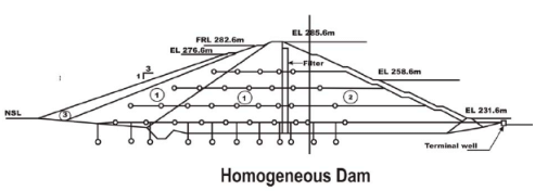
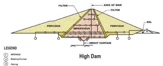
FIGURE 45. Typical installation of piezometers in embankment dams
Structural design of special components
Although maximum value of concrete in gravity dam construction goes into mass concreting, reinforcements are required at some places for resisting tensile stresses. Of these two components are quite important: Galleries and spillway piles. The Bureau of Indian Standards has brought out two codes on the structural design of these components and they are as follows;
- IS: 12966(Part 2)-1990 “Code of practice for galleries and other openings in dams” ( Part 2: Structural design)
- IS: 13551-1992 “Structural design of spillway piers and crest–criteria”
Though the details may be found in the above code it may be mentioned that galleries are openings in the body of the dam that introduce stress concentration in its surroundings. This concentration would be minimum if the openings are circular or nearly so. But for ease of operation, the galleries are mostly rectangular thus accentuating the stress concentration at the corners. Hence reinforcement has to be provided all round the openings, and special care taken where two openings meet, say at the junction of the foundation gallery and an inspection adit. Is 12966(part 2) -1990 gives guidelines for both evaluating the stresses and design of reinforcements. It also illustrates typical layout of placing reinforcements.
As for the spillway piers, they are erected over the crest profile and are provided to divide the spillway into a number of bays so as to control the flow over the spillway by installing gates between two piers. Piers are also used to support the bridge over the spillway for the movement of the gantry crane and normal traffic. IS 13551-1992 helps to identify the forces acting on a pier and method to compute the induced moments and stresses. It also illustrates typical layout of reinforcement in a pier and its junction with the spillway crest.
It may be noted that all reinforced concrete works in concrete dams have to conform to IS 456-2000 “code of practice for plain and reinforced concrete”. The following two Bureau of Indian Standard codes may also be referred to for further details related to training walls, divide walls and spillway anchorages.
- IS 12720-1992 “Criteria for structural design of spillway training and divide walls”
- IS 95-1993 “Design aid for anchorages for spillway structures”
FAQs on Design and Construction of Concrete Gravity Dams (Part - 6) - Civil Engineering (CE)
| 1. What is a concrete gravity dam? |  |
| 2. How are concrete gravity dams constructed? | |
| 3. What are the advantages of concrete gravity dams? | |
| 4. Are there any limitations to the construction of concrete gravity dams? | |
| 5. How are concrete gravity dams maintained? | |


Free
,ppt
,Important questions
,study material
,Semester Notes
,shortcuts and tricks
,Design and Construction of Concrete Gravity Dams (Part - 6) - Civil Engineering (CE)
,Extra Questions
,past year papers
,Previous Year Questions with Solutions
,mock tests for examination
,MCQs
,Design and Construction of Concrete Gravity Dams (Part - 6) - Civil Engineering (CE)
,Exam
,Design and Construction of Concrete Gravity Dams (Part - 6) - Civil Engineering (CE)
,Summary
,Objective type Questions
,practice quizzes
,Viva Questions
,video lectures
,Sample Paper
,


Design and Construction of Concrete Gravity Dams (Part - 6) Free PDF Download
Importance of Design and Construction of Concrete Gravity Dams (Part - 6)
Design and Construction of Concrete Gravity Dams (Part - 6) Notes
Design and Construction of Concrete Gravity Dams (Part - 6) Civil Engineering (CE) Questions
Study Design and Construction of Concrete Gravity Dams (Part - 6) on the App
|
© EduRev
|
Education Revolution
|


|


