Design and Construction of Concrete Gravity Dams (Part -10) - Civil Engineering (CE) PDF Download

Seepage control measures in embankment dam and foundation
One of the basic requirements for the design of an earth or rockfill dam is to ensure safety against internal erosion, piping and excessive pore pressure in the dam. A suitably designed drainage system is therefore essential to satisfy these requirements. The seepage of reservoir water through the body of the dam or at the interfaces of the dam with the foundation or abutment creates two main problems, apart from causing excessive water loss and thereby reducing usable storage of reservoir:
- Seepage force causing excessive water loss
- Piping
Inspite of taking all measures in design as well as construction to minimize seepage, it does take place either through the body of the dam or at interfaces. Whatever may be quantum of seepage, if it is not safely drained away from the toe of embankment dam into nearby drainage, valley, etc, it may lead to failure or heavy damage to the embankment, by way of slips of slopes and/or development of internal erosion leading to formation of sink holes, boiling, settlement, etc, besides creating unfriendly environment on downstream faces and areas of embankment dams.
The drainage system should be so devised that it tackles the problems mentioned in section 4.7.4. The design is mostly governed by type and permeability of base materials as well as filter materials, water depth in reservoir, topographical features of dam site, etc. The conventional types of seepage control and drainage features generally adopted for the embankment dam are:
- Impervious c ore,
- Inclined/vertical f ilter with horizontal filter,
- Network of inner longitudinal drain and cross drains,
- Horizontal f ilter,
- Transition z ones/transition filters,
- Intermediate fi lters,
- Rock toe, and
- Toe drain.
The drainage system may comprise of either one or a combination of more than one of these drainage features, and typical sections are shown for homogeneous dams, in Figure 35 and for zoned dams, in Figure 36. The functions of each of the components are described in the following paragraphs.
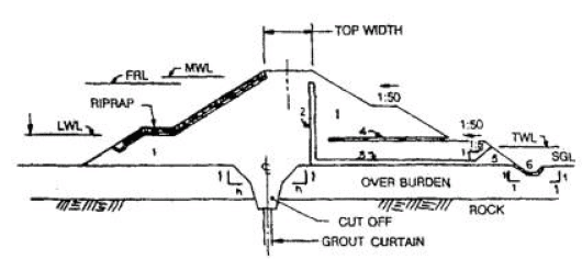
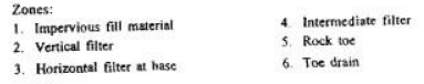
Figure 35. Section of homogenous dam showing seepage control features
Figure 36. Section of zoned dam showing seepage control features
Inclined/Vertical Filter
Inclined or vertical filter abutting downstream face of either impervious core or downstream transition zone is provided to collect seepage emerging out of core/transition zone and thereby keeping the downstream shell relatively dry. In the eventuality of hydraulic fracturing of the impervious core, it prevents the failure of dam by piping.
Horizontal Filter
It collects the seepage from the inclined/vertical filter or from the body of the dam, in the absence of inclined/vertical filter, and carries it to toe drain. It also collects seepage from the foundation and minimizes possibility of piping along the dam seat.
Inner Longitudinal and Inner Cross Drains
When the filter material is not available in the required quantity at reasonable cost, a network of inner longitudinal and inner cross drains is preferred to inclined/vertical filters and horizontal filters. This type of drainage feature is generally adopted for small dams, where the quantity of seepage to be drained away is comparatively small. A typical arrangement of longitudinal and cross drains is shown in Figure 37.
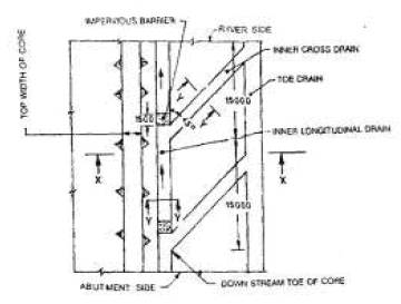
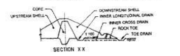
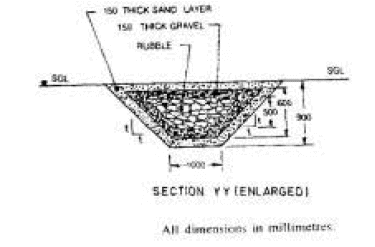
Figure 37. Typical arrangement of inner longitudinal and inner cross drains
Transition Zones and Transition Filters
Transition zones/filters in earth and rockfill dams in the upstream and downstream shells are necessary, when the specified gradation criterion is not satisfied between two adjacent zones. When such zones/filters are placed on either side of the impervious core, they help to minimize failure by internal piping, cracking, etc, that may develop in the core or by migration of fines from the core material.
The filter material used for drainage system shall satisfy the following criteria:
- Filter materials shall be more pervious than the base materials;
- Filter materials shall be of such gradation that particles of base material do not totally migrate through to clog the voids in filter material; and
- Filter material should help in formation of natural graded layers in the zone of base soil adjacent to the filter by readjustment of particles.
Horizontal Filters at Intermediate Levels
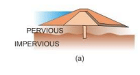
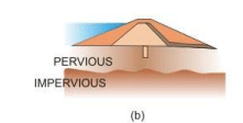
Horizontal filter layers at intermediate levels are sometimes provided in upstream and downstream shells, to reduce pore pressures during construction and sudden drawdown condition and also after prolonged rainfall (see Figure 38).
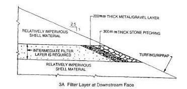
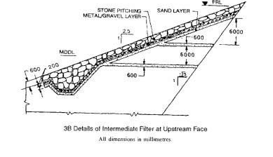
Figure 38. Horizontal filter at intermediate levels;(a) On downstream, and (b) On upstream
The filter layers should be extended upto the outer slopes of the embankment so as to drain out the collected water. These filter layers should not be connected with inclined or vertical filters. A minimum space of 2.0 m or more, should be kept between the face of inclined/vertical filter and downstream intermediate filter. The material of the filter layers should be protected at exposed faces as shown in Figure 38. Details are shown in Figure 39.
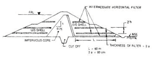
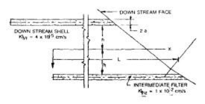
Figure 39. Thickness of horizontal and inverted filters
Rock Toe
The principal function of the rock toe is to provide drainage. It also protects the lower part of the downstream slope of an earth dam from tail water erosion. Rock available from compulsory excavation may be used in construction of the rock toe. Where this is not possible and transportation of rock is prohibitively costly, conventional pitching should be used for protecting the downstream toe of the dam. The top level of the rock toe/pitching should be kept above the maximum tail water level (TWL). In the reach where the ground level at the dam toe is above the maximum tail water level, only conventional pitching should be adopted. The top of such pitching should be kept 1.0 m above the top of horizontal filter, or stripped level, whichever is higher. A zone of coarse filter should be introduced between the rockfill/ pitching and the fine filter. A combination of partial rock toe and pitching may also be considered to effect economy.
Details of rock toe/pitching protection and toe drains are illustrated for various combination of Tail Water Level (TWL) and stripped Ground Level (SGL).
- Rock toe when TWL is higher than SGL (Figure 40)
- Pitching when TWL is higher than SGL (Figure 41)
- Rock toe + pitching when TWL is higher than rock toe (Figure 42)
- Pitching when SGL is above TWL (Figure 43)
- Pitching and lined toe drain (Figure 44)
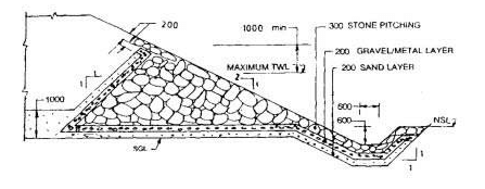
Figure 40. Details of rock toe protection with toe drain where TWL is higher than SGL
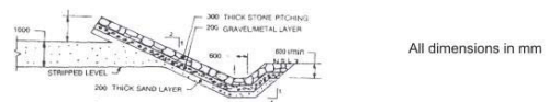
Figure 41. Details of pitching with toe drain where TWL is higher than SGL
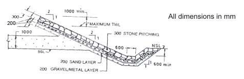
Figure 42, Details of rock toe and pitching with toe drain where TWL is higher than rock toe
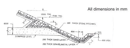
Figure 43. Details pitching with toe drain where SGL is above TWL
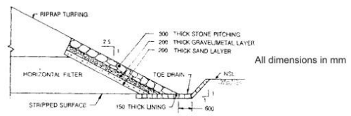
Figure 44. Details of pitching and lined toe drain
Toe Drain
Toe drain is provided at the downstream toe of the earth/rockfill dam to collect seepage from the horizontal filter or inner cross drains, through the foundation as well as the rain water falling on the face of the dam, by suitable means according to site conditions. Additional longitudinal drain and cross drains connected with the toe drain are sometimes provided where outfall conditions are poor. It is preferable to provide the toe drain outside the toe of rock toe, to facilitate visual inspection. The section of the toe drain should be adequate for carrying total seepage from the dam, the foundation and the expected rain water.
Details of the above measures required for seepage control within the body of an embankment dam may be had from the Burean of Indian Standards Code IS: 9429-1999 “Drainage system for earth and rockfill dams-code of practice”.
For the control of seepage below the dam, through the foundation, the Bureau of Indian Standards Code IS: 8414-1977 “Guidelines for design of under-seepage control measures for earth and rockfill dams mention a number techniques. The provision of seepage control in the foundations, as in the body of the dam, is required to control the loss of water to an amount compatible with the purpose of the project, and the elimination of the possibility of a failure of the structure by piping. Many dams have been in successful service for decades in spite of losses of water. Therefore, the first step in rational design of seepage control measures is to estimate the largest quantity of water that may escape if no attempt is made to intercept percolation through the foundation. In many instances, it would be found that interception of the most conspicuously pervious zones would be sufficient. Sometimes, the reservoir bottom may have to be made impervious to reduce the amount of water seeping into ground. In addition, relief wells may be used at downstream to release the building up of excess pore pressure. These methods are described in the following paragraphs.
Positive Cutoff Trench
The positive cutoff trench (Figure 45) consists of an impervious fill placed in a trench formed by open excavation into an impervious stratum. Grouting of the contact zone of the fill and the underlying strata constitutes an integral part of the positive cutoff. Pockets of such size that compaction equipment cannot be operated and pot holes with overhangs should be filled with concrete.
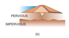
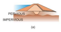
Figure 45. Cut off trenches (a) Positive cut-off (b) Partial cut-off
Concrete Diaphragm
A single diaphragm or a double diaphragm may also be used for seepage control (Figure 46). Concrete cutoff walls placed in slurry trench are not subject to visual inspection during construction, therefore require special knowledge, equipment and skilled workmen to achieve a satisfactory construction.
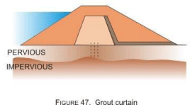
Grout Curtain
Grout Curtain in Pervious Soils: Grouted cutoffs are produced by injection, within the zone assigned to the cutoff, of the voids of the sediments with cement, clay, chemicals, or a combination of these materials. An essential feature of all grouting procedures is successive injection, of progressively finer pockets in the deposit. Inasmuch as grout cannot be made to penetrate the finer materials as long as more pervious pockets are available, the coarser materials are treated first, usually with the less expensive and thicker grouts, whereupon the finer portions are penetrated with less viscous fluids.
Grout Curtain in Rock: Grout curtain in rock admit of routinized treatment if the purpose is only to block the most pervious zones. These can be treated by cement grout with suitable admixtures. Concentrated seepage would generally develop at the base of the positive cutoff. This zone is particularly vulnerable when a narrow base width is used for the cutoff trench in relation to the height of the dam. The depth of the grouted zone would be dependent on the nature of the substrata and their vulnerability to subsurface erosion.
Details about the method of grouting may be had from Bureau of Indian Standards code IS: 11293(Part1)-1985 “Guidelines for the design of grout curtails: Earth and rockfill dams”. An indicative illustration of grout curtain is shown in Figure 47.
Slurry Trench Cutoff Walls
A backhoe or dragline excavates a trench through the pervious deposits down to suitable impervious materials. A bentonite slurry, retained in the trench above the existing ground-water level, prevents the trench walls from caving. After a sufficient length of trench has been excavated and the bottom suitably prepared, back filling begins.
The physical characteristics of the backfill are specially controlled; in general, the backfill should be well-graded, impermeable in place, and sufficiently coarse to minimize post construction settlements. A selected amount of bentonite slurry may be blended with the backfill to improve its properties. The embankment should be suitably designed to resist cracking by differential settlement due to the slurry trench.
Steel Sheet Piles
Sheet piles are useful as barrier to arrest internal erosion. But they have proved to be rather ineffective as a positive means of controlling seepage through pervious deposits. Even if sheet pile cutoffs are intact they are not water-tight because of leakage across the interlocks. In addition the locks may break because of defects in the steel or when a pile hits an obstacle. Once the lock is split, the width of the gap increases rapidly with increasing depth and may assume dimensions of a few meters.
Upstream Impervious Blanket
If a positive cutoff is not required, or is too costly, an upstream impervious blanket combined with relief wells in the downstream section may be used. Filter trenches supplement relief wells in heterogeneous deposits and in zones of seepage concentrations. An upstream blanket may result in major project economies, particularly if the only alternative consists of deep grout curtains or concrete cutoff walls. Since alluvial deposits in river valleys are often overlain by a surface layer of relatively impervious soils, it is advantageous if this natural impervious blanket can be incorporated into the overall scheme of seepage control.
Relief Wells
Relief wells are an important adjunct to most of the preceding basic schemes for seepage control. They are used not only in nearly all cases with upstream impervious blankets, but also along with other schemes, to provide additional assurance that excess hydrostatic pressures do not develop in the downstream portion of the dam, which could lead to piping. They also reduce the quantity of uncontrolled seepage flowing downstream of the dam and, hence, they control to some extent the occurrence and/or discharge of springs. Relief wells should be extended deep enough into the foundation so that the effects of minor geological details on performance are minimized. It is necessary to note the importance of continuous observation and maintenance of relief wells, if they are essential to the overall system of seepage control Details of relief wells may be had from Bureau of Indian Standards code IS: 5050-1968 “Code of Practice for design, construction and maintenance of relief wells”. A view of the relief well is shown in Figure 48.
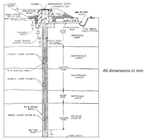
Figure 48. A typical relief well
FAQs on Design and Construction of Concrete Gravity Dams (Part -10) - Civil Engineering (CE)
| 1. What is the design process for concrete gravity dams? |  |
| 2. How is the construction of concrete gravity dams carried out? | |
| 3. What are the advantages of using concrete for gravity dams? | |
| 4. How are the stability and safety of concrete gravity dams ensured? | |
| 5. How long does it take to construct a concrete gravity dam? | |


Exam
,Important questions
,mock tests for examination
,MCQs
,Extra Questions
,Sample Paper
,Design and Construction of Concrete Gravity Dams (Part -10) - Civil Engineering (CE)
,practice quizzes
,Design and Construction of Concrete Gravity Dams (Part -10) - Civil Engineering (CE)
,past year papers
,shortcuts and tricks
,video lectures
,Summary
,Design and Construction of Concrete Gravity Dams (Part -10) - Civil Engineering (CE)
,Semester Notes
,Free
,study material
,Objective type Questions
,Viva Questions
,ppt
,Previous Year Questions with Solutions
;


Design and Construction of Concrete Gravity Dams (Part -10) Free PDF Download
Importance of Design and Construction of Concrete Gravity Dams (Part -10)
Design and Construction of Concrete Gravity Dams (Part -10) Notes
Design and Construction of Concrete Gravity Dams (Part -10) Civil Engineering (CE) Questions
Study Design and Construction of Concrete Gravity Dams (Part -10) on the App
|
© EduRev
|
Education Revolution
|


|


within 7 days!