Summary: Resultant of Force System | Engineering Mechanics - Civil Engineering (CE) PDF Download
Resultant
Resultant is a single force that will replace a system of forces and produces the same effect on the rigid body as that of the system of forces.
A. Resultant of Two Concurrent Forces - Parallelogram Law of Forces
Sign Conventions The following sign conventions shall be used throughout the book 1. Upward forces are considered as positive, whereas the downwards as negative. 2. Forces acting towards right are considered as positive, whereas those towards left as negative. |
Problems
Q1. Find the magnitude of the two forces, such that if they act at right angles, their resultant is √10 N. But if they Act at 60°, their resultant is √13 N.
Q2. The greatest and least resultants of two forces F1 and F2 are 17 N and 3 N respectively. Determine the angles between them when their resultant is √149 N
Q3. A screw eye is subjected to two forces F1 and F2 as shown in figure. Determine the magnitude and direction of the resultant force by parallelogram method

Q4. The two structural members, one of which is in tension and the other in compression, exert the indicated forces on joint O. Determine the magnitude of the resultant R of the two forces and the angle which R makes with the positive x-axis.

Resolution Of Forces
The replacement of a single force by a several components which will be equivalent in action to the given force is called resolution of a force.
Forces can be resolved in any 2 directions. However, it is convenient to resolve them into the two orthogonal components (mutually perpendicular directions)
Resolution of Coplanar Forces in Rectangular Coordinates

B. Resultant of Concurrent Coplanar Force Systems 1. Resolve all the forces into x and y components 2. Add the components of forces along the x and y axes with proper sense of direction. 3. Find the resultant and inclination of the forces
|

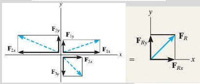

Note : 1. If both FRx and FRy are positive, the resultant lies in the first quadrant 2. If both FRx and FRy are negative the resultant lies in the third quadrant 3. If FRx is positive and FRy is negative, the resultant lies in the fourth quadrant 4. If FRx is negative and FRy is positive, the resultant lies in the second quadrant
|

Problems for Practice
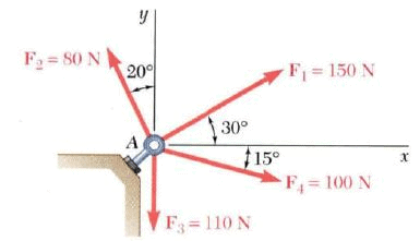
Q1. Four forces act on bolt A as shown. Determine the resultant of the force on the bolt.
Q2. If the magnitude of the resultant force is to be 9 kN directed along the positive x axis, determine the magnitude of force T acting on the eyebolt and its angle.

Q3. Determine the resultant of the 3 forces acting on the bracket and its direction.

Q4. The forces 20 N, 30 N, 40 N, 50 N and 60 N are acting at one of the angular points of a regular hexagon, towards the other five angular points, taken in order. Find the magnitude and direction of the resultant force.

Q5. If Φ = 30 and the resultant force acting on the gusset plate is directed along the positive x axis, determine the magnitudes of F2 and the resultant force.

Q6. Determine the resultant of the forces shown below

Q7. Determine the resultant of the forces acting on the ring shown in figure.

Q8. Find the resultant of the three concurrent forces as shown on figure.

Q9. Find the magnitude and direction of the resultant of the following forces.
i. 20 N inclined at 30° towards North of East.
ii. 25 N towards North.
iii. 30 N towards North West and
iv. 35 N inclined at 40° towards South of West.
Moment
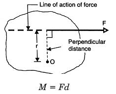
The tendency of a force to rotate the body in the direction of its application a force about a point that is not on the line of action of the force is called Moment of force or simply moment.
Moment is also referred to as torque.
Scalar Formulation
Moment is a vector quantity whose direction is perpendicular to the plane of the body. The right-hand rule is used to establish the sense of direction of moment. Throughout the text, clockwise moments are taken as positive while anti-clockwise as negative.

Varignon’s Theorem or Principle of Moments
The moment of a force about any point is equal to the sum of the moments of the components of the force about the same point.”

Couple
The moment produced by two equal, opposite, and non-collinear forces is called a couple. The perpendicular distance between the lines of action of the two and opposite parallel forces is known as arm of the couple.

A couple can be represented by a vector with magnitude and direction equal to the moment of the couple.

Practical Examples : Force apllied to a handle of steering wheel
|

Differences between Moment and Couple
| Moment | Couple |
1 Moment is the tendency of force to rotate a body with the given point or axis 2 It is produced by forces not passing through point of rotation axis 3 There is a resultant force acting on the body in the direction of force and rotate the body. 4 To balance the force causing moment, equal and opposite force is required. 5 For example, To tight the nut by spanner To open or close the door | 1 Two equal and opposite forces whose lines of action are different form a couple 2 It is produced by the two equal and opposite parallel, non collinear forces. 3 Resultant force of couple is zero. Hence, body does not move, but rotate only. 4 Couple cannot be balanced by a single force, it can be balanced by a couple only. 5 For example, To rotate the key in lock To open or close the wheel valve of water line To rotate the steering wheel of car. |
C. Resultant of Coplanar Non-concurrent Force Systems
A system of several forces and couple moments acting on a body can be reduced to equivalent single resultant force acting at a point O and a resultant couple moment.

X-Y Intercepts Intercepts are the points/coordinates where the line of action meets the corresponding axes.
|

D. Resolution of Force Into Force and Couple System
Suppose we have to sift he force from point A to B. The procedure to be followed
1. Apply 2 equal and opposite force at point A parallel to force B of the same magnitude
2. If the points are separated by a distance d, the opposite forces F and –F form a couple retaining force F at point B in the same direction as A

Problems
Q1. Replace the force system acting on the beam by an equivalent force and couple at point B.

Q2. Reduce the following force system into
a) A single force
b) Resultant force and couple acting at point A.
c) Resultant force and couple acting at point B.
d) Resultant force and couple acting at point C.

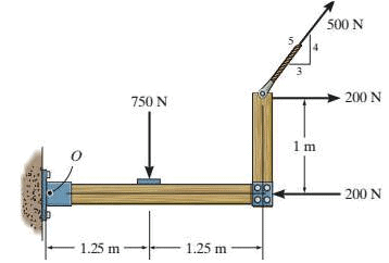
Q3. Replace the force system by a resultant force and couple moment at point O.
Q4. Two coplanar forces P and Q are shown in figure. Assume all squares of the same size.
i) If P = 4 kN, find the magnitude and direction of Q if their resultant passes through E
ii) If Q = 110 kN, find the magnitude and direction of P if their resultant passes through F

Representation of Force
There are two ways of representation of force. The method used depends on the type of problem being solved and the easiest approach to finding a solution.
- Scalar Notation
- Vector Notation
Vector Notation Of Forces
1. Two Dimensional Force Systems (Coplanar Forces) It is also possible to represent the x and y components of a force in terms of Cartesian unit vectors i and j.


where the scalars Fx and Fy are the x and y scalar components of the vector F.
2. Three Dimensional Force Systems(Non-Coplanar Forces)
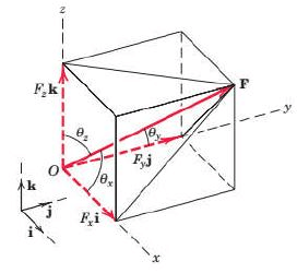

Unit Vector Vectors having unit magnitude and represents only the direction of vectors is called a unit vector. It is usually denoted by n. A vector V may be expressed mathematically by multiplying its magnitude V by a vector n whose magnitude is one and whose direction coincides with that of V.
The unit vectors along the Rectangular Coordinate axis x, y and z are
|


Problems
Q1. A force vector F = 700i + 1500j is applied to a bolt. Determine the magnitude of force and the angle it forms with the horizontal.
Q2. A force of 500 N forms angles 600, 450 and 1200 respectively with x, y and z axes. Write the vector form of force.
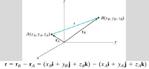
Position Vector A position vector r is defined as a fixed vector which locates a point in space relative to another point. a) Position Vector of P relative to origin
b) Position vector of B with respect to A
|


A. Resultant of Non Coplanar Forces -by Vector Notation
1. Resultant of Non Coplanar Concurrent Forces
In vector notation, the scalar components of the resultant vector can be obtained by adding algebraically the sum of the corresponding scalar components of the force vectors.

where

B. Moment and Couple – in Vector Notation
Moment
Moment is a vector quantity whose direction is perpendicular to the plane of the body. The right-hand rule is used to establish the sense of direction of moment.
Vector Formulation

Varignon’s Theorem
Vector Formulation 
Couple
Vector Formulation

Couple vectors are free vectors, i.e., the point of application is not significant.

Note : Cross Product of vectors
|


2. Resultant of Non Coplanar Non-Concurrent Forces ProblemsQ Q1. A table exerts the four forces shown on the floor surface. Reduce the force system to a force– couple system at point O. Determine the resultant of the following force and its location
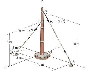
Q2. Replace the two forces acting on the post by a resultant force and couple moment at point O. Express the results in Cartesian vector form.
|

C. Equilibrium of Non Coplanar Forces – by Vector Notation


1. Equilibrium of Non-Coplanar Concurrent Forces
In vector notation, the equation of equilibrium can be summarized as

|
24 videos|59 docs|53 tests
|
FAQs on Summary: Resultant of Force System - Engineering Mechanics - Civil Engineering (CE)
| 1. What is the resultant of a force system? |  |
| 2. How can the resultant of a force system be calculated? | |
| 3. Why is it important to determine the resultant of a force system? | |
| 4. Can the resultant of a force system be zero? | |
| 5. What are some real-life applications of analyzing the resultant of a force system? | |

|
2K Views |

|
4.64/5 Rating |

|
Dec 22, 2024 Last updated |

|
Explore Courses for Civil Engineering (CE) exam
|
|
study material
,past year papers
,practice quizzes
,Semester Notes
,Free
,mock tests for examination
,Sample Paper
,Summary
,Summary: Resultant of Force System | Engineering Mechanics - Civil Engineering (CE)
,Previous Year Questions with Solutions
,video lectures
,Summary: Resultant of Force System | Engineering Mechanics - Civil Engineering (CE)
,Objective type Questions
,MCQs
,Exam
,Extra Questions
,Viva Questions
,Important questions
,ppt
,shortcuts and tricks
,Summary: Resultant of Force System | Engineering Mechanics - Civil Engineering (CE)
;


Summary: Resultant of Force System Free PDF Download
Importance of Summary: Resultant of Force System
Summary: Resultant of Force System Notes
Summary: Resultant of Force System Civil Engineering (CE) Questions
Study Summary: Resultant of Force System on the App
|
© EduRev
|
Education Revolution
|


|


