Cartesian Vectors | Engineering Mechanics - Civil Engineering (CE) PDF Download
| Table of contents |
|
| Cartesian Vectors |
|
| Cartesian Force Vectors |
|
| Addition of Forces. |
|
| Resolution of Forces |
|

Cartesian Vectors
- Cartesian vectors are like arrows in space that tell you two important things: which way to go and how far. Imagine three lines crossing each other at right angles, like a corner of a room. These lines are the x, y, and z axes. A vector is just a set of three numbers that tells you how much to move along each of these lines.
- So, if you have a vector like ⟨3, 2, -1⟩, it means you move 3 steps to the right, 2 steps up, and 1 step back. These little packages of numbers help us understand how things move and push in the world around us. Scientists and engineers use them to make machines work better and to figure out how things move in space.
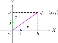 Cartesian Vector
Cartesian Force Vectors
- Cartesian force vectors represent the directed forces acting on objects in space. In the Cartesian coordinate system, forces are described by their components along the x, y, and z axes, denoted as ⟨Fx, Fy, Fz⟩. These components indicate the magnitude and direction of the force along each axis.
- For instance, a force vector of <i>⟨10, 5, -3⟩</i> signifies a force of 10 units along the positive x-axis, 5 units along the positive y-axis, and 3 units along the negative z-axis.
- Any force F can be written in the form of a Cartesian vector. Such an expression uses the addition of the force’s component vectors in the x, y, and z directions of the axes of the right-hand coordinate. If the magnitude of its component in the x direction is Fx, in the y direction Fy, an in the z direction Fz, then F is expressed as
F = Fxi +Fyj + Fzk
wherei, j, and k are the Cartesian unit vectors.
Expressing A Force Vector By Using Its Magnitude And Two Points On Its Line Of Action.
- The Cartesian vector expression for a force is often obtained by using the Cartesian position vector that gives the Cartesian unit vectors corresponding to the direction concerned. For example, the force F has a line of action that passes through points P(x1,y1,z1) and Q(x2,y2,z2).
- Let the position vector r that points from P to Q describes the relative position between P and Q. From the diagram, we obtain the relationship
- r = –r1 + r2
- However, we can formulate the relationships r1 = x1i + y1j + z1k and r2 = x2i + y2j + z2k. By inserting these relationships into the terms for r1 and r2 in the equation above, we get
- r = (x2 – x1)i + (y2 – y1)j + (z2 – z1)k …..(2.2)
- Hence the components of r in the x, y, and z directions are obtained by subtracting the coordinates of the tail from those of the heads. Note that if the coordinates of Q are subtracted from those of P, we will get the vector –r.
- A force of magnitude F and having its line of action, direction, and sense corresponding to the unit vector s in Figure 2.3 can thus be expressed in the Cartesian vector form by writing F = Fs and then expanding the expression on the right of the equal sign.
- The coordinate direction angles for the line of action of F are obtained from the cosine direction relationship for s
Addition of Forces.
The concept of force resultant can be applied to a concurrent force system which is written in the Cartesian vector form. If P is the resultant of F1, F2, F3, … hence
P =ΣFi
= (F1x + F2x + …)i + (F1y + F2y + …)j + (F1z + F2z + …)k
= ΣFixi + ΣFiyj + ΣFizk (2.5)
whereΣFix, ΣFiy, and ΣFiz are the sums of the magnitudes of the forces in the corresponding direction.
Resolution of Forces
Any force can be resolved into its components. There are a number of methods that can be used to resolve a force. The method use depends on the problem at hand. The different methods are described below.
2.8.1. Parallelogram Law
A force acting at any point can be resolved into components that act in two desired directions through the parallelogram law. Force F in Figure 2.12(a), for example, can be replaced by two components acting in directions 1 and 2. The resolution is implemented by drawing a parallelogram with F as the diagonal and its two non-parallel sides along directions 1 and 2,
Note that resolution is the reverse process of adding two forces into their resultant. Hence the resolution involves six quantities, i.e. the magnitude and direction of F and of the two components, where two of them can be determined when the other four are known.
Rectangular components. When force F is resolved into perpendicular directions, we obtain the rectangular components. This is shown in Figure 2.13 for a 2D case, where the respective perpendicular directions are represented by the x-axis and the y-axis. In this case, we get
Fx = F cos θ
Fy = F sin θ
where θ = tan-1 (Fy/Fx)
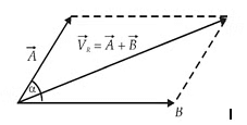
Addition Of Forces. Forces can be added by using their components, normally the rectangular components in the Cartesian directions. Consider forces F1 and F2 that are concurrent at O being added using the force polygon, Figure 2.14(a). The resultant P is
P = F1 + F2
|
23 videos|61 docs|53 tests
|
FAQs on Cartesian Vectors - Engineering Mechanics - Civil Engineering (CE)
| 1. What are Cartesian vectors? |  |
| 2. How are Cartesian vectors represented mathematically? | |
| 3. What are the components of a Cartesian vector? | |
| 4. How do you add or subtract Cartesian vectors? | |
| 5. How are Cartesian vectors used in physics and engineering? | |


Extra Questions
,Semester Notes
,shortcuts and tricks
,Cartesian Vectors | Engineering Mechanics - Civil Engineering (CE)
,Free
,video lectures
,Exam
,Sample Paper
,past year papers
,practice quizzes
,Previous Year Questions with Solutions
,Summary
,Objective type Questions
,Viva Questions
,Important questions
,ppt
,Cartesian Vectors | Engineering Mechanics - Civil Engineering (CE)
,Cartesian Vectors | Engineering Mechanics - Civil Engineering (CE)
,study material
,MCQs
,mock tests for examination
;


Cartesian Vectors Free PDF Download
Importance of Cartesian Vectors
Cartesian Vectors Notes
Cartesian Vectors Civil Engineering (CE) Questions
Study Cartesian Vectors on the App
|
© EduRev
|
Education Revolution
|


|


