Free Body Diagram in 3D | Engineering Mechanics for Mechanical Engineering PDF Download
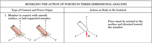
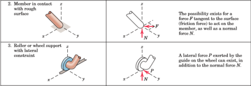
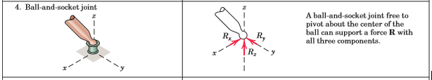
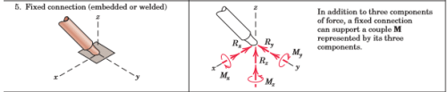
The summations in Eqs. 3/3 include the effects of all forces on the body under consideration. We learned in the previous article that the free-body diagram is the only reliable method for disclosing all forces and moments which should be included in our equilibrium equations. In three dimensions the free-body diagram serves the same essential purpose as it does in two dimensions and should always be drawn. We have our choice either of drawing a pictorial view of the isolated body with all external forces represented or of drawing the orthogonal projections of the free-body diagram. Both representations are illustrated in the sample problems at the end of this article. The correct representation of forces on the free-body diagram requires a knowledge of the characteristics of contacting surfaces. These characteristics were described in Fig. 3/1 for two-dimensional problems, and their extension to three-dimensional problems is represented in Fig. 3/8 for the most common situations of force transmission. The representations in both Figs. 3/1 and 3/8 will be used in three-dimensional analysis. The essential purpose of the free-body diagram is to develop a reliable picture of the physical action of all forces (and couples if any) acting on a body. So it is helpful to represent the forces in their correct physical sense whenever possible.
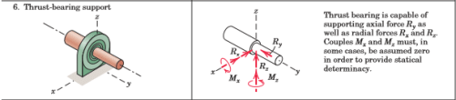
In this way, the free-body diagram becomes a closer model to the actual physical problem than it would be if the forces were arbitrarily assigned or always assigned in the same mathematical sense as that of the assigned coordinate axis. For example, in part 4 of Fig. 3/8, the correct sense of the unknowns Rx and Ry may be known or perceived to be in the sense opposite to those of the assigned coordinate axes. Similar conditions apply to the sense of couple vectors, parts 5 and 6, where their sense by the right-hand rule may be assigned opposite to that of the respective coordinate direction. By this time, you should recognize that a negative answer for an unknown force or couple vector merely indicates that its physical action is in the sense opposite to that assigned on the free-body diagram. Frequently, of course, the correct physical sense is not known initially, so that an arbitrary assignment on the free-body diagram becomes necessary.
Categories of Equilibrium
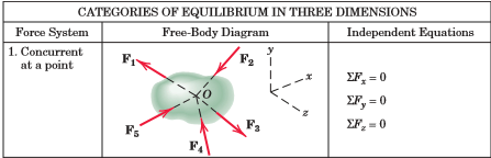
Application of Eqs. 3/3 falls into four categories which we identify with the aid of Fig. 3/9. These categories differ in the number and type (force or moment) of independent equilibrium equations required to solve the problem.
Category 1, equilibrium of forces all concurrent at point O, requires all three force equations, but no moment equations because the moment of the forces about any axis through O is zero.
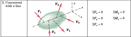
Category 2, equilibrium of forces which are concurrent with a line, requires all equations except the moment equation about that line, which is automatically satisfied.
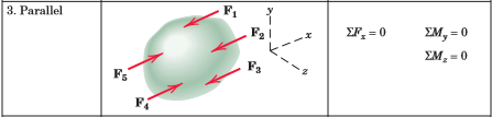
Category 3, equilibrium of parallel forces, requires only one force equation, the one in the direction of the forces (x-direction as shown), and two moment equations about the axes (y and z) which are normal to the direction of the forces.
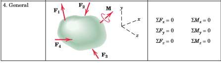
Category 4, equilibrium of a general system of forces, requires all three force equations and all three moment equations. The observations contained in these statements are generally quite evident when a given problem is being solved.
|
24 videos|70 docs|58 tests
|
FAQs on Free Body Diagram in 3D - Engineering Mechanics for Mechanical Engineering
| 1. What is a free body diagram in 3D? |  |
| 2. How do you create a free body diagram in 3D? | |
| 3. What is the purpose of a free body diagram in 3D? | |
| 4. Can a free body diagram in 3D be used to analyze rotational motion? | |
| 5. What are some common mistakes to avoid when creating a free body diagram in 3D? | |

|
4.75/5 Rating |

|
Dec 22, 2024 Last updated |
|
24 videos|70 docs|58 tests
|

|
Explore Courses for Mechanical Engineering exam
|
|
Free Body Diagram in 3D | Engineering Mechanics for Mechanical Engineering
,Exam
,Important questions
,Objective type Questions
,Previous Year Questions with Solutions
,Free Body Diagram in 3D | Engineering Mechanics for Mechanical Engineering
,past year papers
,Sample Paper
,MCQs
,ppt
,mock tests for examination
,Semester Notes
,shortcuts and tricks
,Free
,Viva Questions
,Summary
,practice quizzes
,video lectures
,study material
,Free Body Diagram in 3D | Engineering Mechanics for Mechanical Engineering
,Extra Questions
;


Free Body Diagram in 3D Free PDF Download
Importance of Free Body Diagram in 3D
Free Body Diagram in 3D Notes
Free Body Diagram in 3D Mechanical Engineering Questions
Study Free Body Diagram in 3D on the App
|
© EduRev
|
Education Revolution
|


|


