Principles of Moments: Forces, Points and Couples | Engineering Mechanics - Civil Engineering (CE) PDF Download

Principle of Moments or Varignon’s Theorem
Varignon’s Theorem states that the moment of a force about any point is equal to the algebraic sum of the moments of its components about that point.
Principal of moments states that the moment of the resultant of a number of forces about any point is equal to the algebraic sum of the moments of all the forces of the system about the same point.
Proof of Varignon’s Theorem
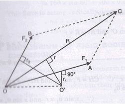
Fig. 2.34 (a)
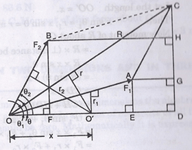
Fig.2.34 (b)
Fig2.34 (a) shows two forces Fj and F2 acting at point O. These forces are represented in magnitude and direction by OA and OB. Their resultant R is represented in magnitude and direction by OC which is the diagonal of parallelogram OACB. Let O’ is the point in the plane about which moments of F1, F2and Rare to be determined. From point O’, draw perpendiculars on OA, OC and OB.
Let r1= Perpendicular distance between F1 and O’.
r2= Perpendicular distance between R and O’.
r3= Perpendicular distance between F2 and O’.
Then according to Varignon’s principle;
Moment of R about O’ must be equal to algebraic sum of moments of F1 and F2about O’.
R * r = F1 * r1 + F2 * r2
Now refer to Fig. 2.34 (b). Join OO’ and produce it to D. From points C, A and B draw perpendiculars on OD meeting at D, E and F respectively. From A and B also draw perpendiculars on CD meeting the line CD at G and H respectively.
Let θ1 = Angle made by F; with OD,
θ = Angle made by R with OD, and
θ2 = Angle made by F2with OD.
In Fig. 2.34 (b), OA = BC and also OA parallel to BC, hence the projection of OA and BC on the same vertical line CD will be equal i.e., GD = CH as GD is the projection of OA on CD and CH is the projection of BC on CD.
Then from Fig. 2.34 (b), we have
P1 sin θ1 = AE = GD = CH
F1 cos θ1 = OE
F2 sin θ1 = BF = HD
F2 cos θ2 = OF = ED
(OB = AC and also OB || AC. Hence projections of OB and AC on the same horizontal line OD will be equal i.e., OF = ED)
R sin θ =CD
R cos θ =OD
Let the length OO’ = x.
Then x sin θ1 = r, x sin θ = r and x sin θ2 = r2
Now moment of R about O’
= R * (distance between O’ and R) = R * r
= R * x sin θ (r = x sin θ)
=(R sin θ) * x
= CD * x (Rsin θ = CD)
= (CH +HD)* x
= (F1 sin θ1 + F2 sin θ2) * x ( CH = F1 sin θ1 and HD = F2 sin θ2)
= F1* x sin θ1 + F2* x sin θ2
= F1 *r1 + F2 *r2 ( x sin θ1 = r1 and x sin θ2 = r2)
= Moment of F1about O’ + Moment of F2about O’.
Hence moment of R about any point in the algebraic sum of moments of its components i.e., F1and F2)about the same point. Hence Varignon’s principle is proved.
The principle of moments (or Varignon’s principle) is not restricted to only two concurrent forces but is also applicable to any coplanar force system, i.e., concurrent or non-concurrent or parallel force system.
Moment of Force about a Point
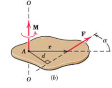
The moment of a force is only defined with respect to a certain point P (it is said to be the "moment about P"), and in general when P is changed, the moment changes. However, the moment (torque) of a couple is independent of the reference point P: Any point will give the same moment. In other words, a torque vector, unlike any other moment vector, is a "free vector".
(This fact is called Varignon's Second Moment Theorem.)
The proof of this claim is as follows: Suppose there are a set of force vectors F1, F2, etc. that form a couple, with position vectors (about some origin P) r1, r2, etc., respectively. The moment about P is
M = r1 * F1 + r2* F2 + r3* F3 + ..
Now we pick a new reference point P' that differs from P by the vector r. The new moment is
M’ = (r1 + r)x F1 + (r2 + r)x F2 + (r3 + r)x F3 + ...
Now the distributive property of the cross product implies
M’ = (r1 x F1 + r2 x F2 + r3 x F3+ ….) + r x (F1 + F2 +F3 + ….)
However, the definition of a force couple means that
F1 + F2 +F3 +...= 0
Therefore,
M’ = r1 x F1 + r2 x F2 + r3 x F3+ .. =M
This proves that the moment is independent of reference point, which is proof that a couple is a free vector.
Couple
In mechanics, a couple is a system of forces with a resultant (a.k.a. net or sum) moment but no resultant force. A better term is force couple or pure moment. Its effect is to create rotation without translation, or more generally without any acceleration of the centre of mass. In rigid body mechanics, force couples are free vectors, meaning their effects on a body are independent of the point of application.
The resultant moment of a couple is called a torque. This is not to be confused with the term torque as it is used in physics, where it is merely a synonym of moment. Instead, torque is a special case of moment.
A couple is a pair of forces, equal in magnitude, oppositely directed, and displaced by perpendicular distance or moment.
The simplest kind of couple consists of two equal and opposite forces whose lines of action do not coincide. This is called a "simple couple". The forces have a turning effect or moment called a torque about an axis which is normal (perpendicular) to the plane of the forces. The SI unit for the torque of the couple is newton metre.
If the two forces are F and −F, then the magnitude of the torque is given by the following formula:
τ = Fd
where
τ is the moment of couple
F is the magnitude of one of the forces
d is the perpendicular distance between the forces, sometimes called the arm of the couple
The magnitude of the torque is always equal to F d, with the direction of the torque given by the unit vector , which is perpendicular to the plane containing the two forces. When d is taken as a vector between the points of action of the forces, then the couple is the cross product of d and F, i.e.
τ =|d*F|.
|
24 videos|69 docs|53 tests
|
FAQs on Principles of Moments: Forces, Points and Couples - Engineering Mechanics - Civil Engineering (CE)
| 1. What is the Principle of Moments? |  |
| 2. How is the Principle of Moments applied in mechanics? | |
| 3. How can the Principle of Moments be used to balance a see-saw? | |
| 4. What are the key factors to consider when applying the Principle of Moments to solve problems? | |
| 5. How does the Principle of Moments relate to real-life applications such as bridge construction or lifting heavy objects? | |


practice quizzes
,shortcuts and tricks
,Objective type Questions
,Extra Questions
,Semester Notes
,study material
,Points and Couples | Engineering Mechanics - Civil Engineering (CE)
,Sample Paper
,Important questions
,past year papers
,mock tests for examination
,Free
,Previous Year Questions with Solutions
,Points and Couples | Engineering Mechanics - Civil Engineering (CE)
,Viva Questions
,ppt
,Principles of Moments: Forces
,Points and Couples | Engineering Mechanics - Civil Engineering (CE)
,Principles of Moments: Forces
,Summary
,Principles of Moments: Forces
,video lectures
,Exam
,MCQs
;


Principles of Moments: Forces, Points and Couples Free PDF Download
Importance of Principles of Moments: Forces, Points and Couples
Principles of Moments: Forces, Points and Couples Notes
Principles of Moments: Forces, Points and Couples Civil Engineering (CE) Questions
Study Principles of Moments: Forces, Points and Couples on the App
|
© EduRev
|
Education Revolution
|


|


within 7 days!