Moment of Force on a Rigid Body | Engineering Mechanics - Civil Engineering (CE) PDF Download
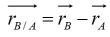
1.- Kinematics. Types of motion:Translation, Rotation about a fixed axis , General Plane Motion, Motionabout a fixed pint, General Motion
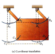
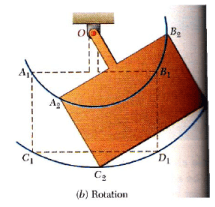
Exercise: Distinguish between curvilinear translation and rotation about a fixed axis
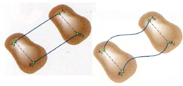
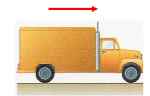
Translation.A motion is said to be a translation if any straight line inside the body keeps the same direction during the movement. All the particles forming the body move along parallel paths. If these paths are straight lines, the motion is said a rectilinear translation; if the paths are curved lines, the motion is a curvilinear motion
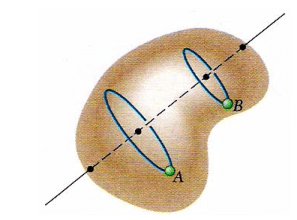
Rotation about a fixed axis. The particles forming the rigid body move in parallel planes along circles centered on the same fixed axis. If this axis, called the axis of rotation intersects the rigid body, the particles located on the axis have zero velocity and zero acceleration
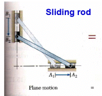
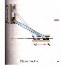
General Plane Motion. Any plane motion which is neither a translation or a rotation is referred as a general plane motion. Plan motion is that in which all the particles of the body move in parallel planes. Translation and rotation are plane motions.
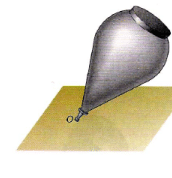

Motion about a fixed point. The three-dimensional motion of a rigid body attached at a fixed point, for example, the motion of a top on a rough floor, is known as motion about a fixed point.
General Motion Any motion of a rigid body which does not fall in any of the cathegories above described.
Exercise: Identify different types of motion
Translation. Motion equations Fig. 15.1 Fig. 15.7 pag 918
Conclusion: A rigid body in translation can be considered as a particle
will be constant in magnitude (rigid body) and in direction (translation motion), then
the derivative of  is zero

When a rigid body is in translation all the points of the body have the same velocity and the same acceleration.
Rotation about a fixed axis.
Motion equations. Velocity
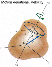
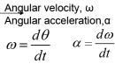
Angular velocity and angular acceleration are invariants. They are the same for all points of the solid. They are a characteristic of the rotating motion of the solid
Basic relationships curvilinear motion arc angle x radius
Where angle is in radians!!! |

Exercise: A compact disk rotating at 500 rev/min is scanned by a laser that begins at the inner radius of about 2.4 cm and moves out the edge at 6.0 cm. Which is the linear (tangential) velocity of the disk where the laser beam strikes: (a) at the beginning of scanning and (b) at the end?. The same for acceleration
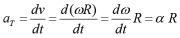
Rotation about A Fixed Axis. Motion equations. Acceleration 
|
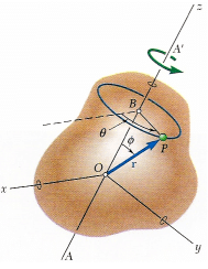
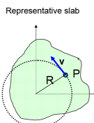
Representative slab
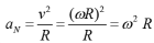
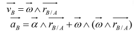
Rotation about a Fixed Axis. The Vector Motion Equations
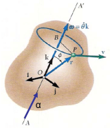
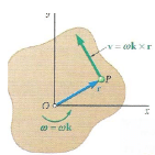
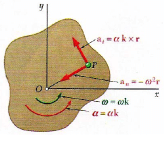
Vector expressions for velocity and acceleration in rotation about a fixed axis
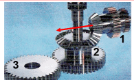
The red arrow shows the angular velocity of the horizontal gear 1. Draw the angular velocity for the other gear, 2 and 3. Solve the problem with quantitative values: ω1 = 500 rev/min; R1 = 2 cm ω2 = ? rev/min; R2 = 5 cm; R´2=10 cm ω3 = ? rev/min; R4 = 10 cm; |
 The bucket falls from the rest with a constant linear acceleration of 0.3 g. (a) Estimate the speed of the bucket after 5 seconds and the fallen distance. (b) Compute the angular acceleration of the pulley © How fast will it rotate after 5 s. The bucket falls from the rest with a constant linear acceleration of 0.3 g. (a) Estimate the speed of the bucket after 5 seconds and the fallen distance. (b) Compute the angular acceleration of the pulley © How fast will it rotate after 5 s. |
 Gear 1 rotates clockwise at angular velocity of 12 rad/s. How fast will gear 2 and 3 rotate. Data: R1:5 cm; R2:10 cm; R3:20 cm. Gear 1 rotates clockwise at angular velocity of 12 rad/s. How fast will gear 2 and 3 rotate. Data: R1:5 cm; R2:10 cm; R3:20 cm. |
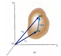
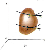
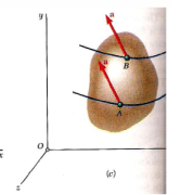
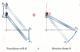
General Plane Motion. Any general plane motion can be considered as a translation plus a rotation
| Euler´s Theorem |
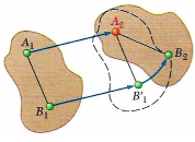
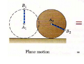
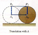
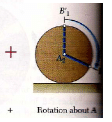
General Plane Motion. Any general plane motion can be considered as a translation plus a rotation
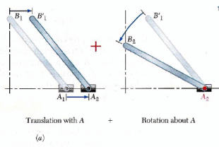
Angular velocity and angular acceleration of rod are independent of the selected point to rotate
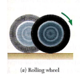
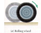
Rolling without slipping.
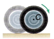
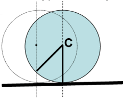
As the wheel of radius R rotates through angle θ, the point of the contact between the wheel and the plane moves a distance s that is related with θ by s= θ R.
If there is no sliding, the distance traveled by point C is exactly the same s.
Rolling without slipping. s = θR vc = ω R ac = αR |
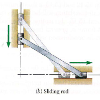
Rolling with slipping. An object slides and rolls
Rolling with slipping. s ≠θ R vc ≠ωR ac≠ α R |
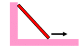
Find the angular velocity of sliding stair of length 3 m, when the velocity of contact point with the soil is 3 m/s. The angles between the stair and the floor is 45º
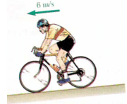
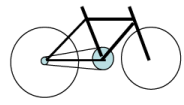
A bicycle travels with a speed of 40 km/h. How fast the cycle rider pedals in rev/min?. Data: Sprocket radius: 2.5 cm; Front gear radius: 10 cm; rear wheel radius: 40 cm |
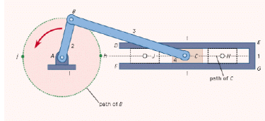
The slider-crank mechanism converts the rotational motion of crank in linear motion of slider. Find the relationship between the angular velocity of crank and the linear velocity of slider piston
|
24 videos|59 docs|53 tests
|
FAQs on Moment of Force on a Rigid Body - Engineering Mechanics - Civil Engineering (CE)
| 1. What is the moment of force on a rigid body? |  |
| 2. How is the moment of force calculated? | |
| 3. What are the units of moment of force? | |
| 4. How does the moment of force affect the rotation of a rigid body? | |
| 5. What factors can influence the moment of force on a rigid body? | |

|
4.65/5 Rating |

|
Dec 22, 2024 Last updated |

|
Explore Courses for Civil Engineering (CE) exam
|
|
video lectures
,Previous Year Questions with Solutions
,Sample Paper
,Exam
,Moment of Force on a Rigid Body | Engineering Mechanics - Civil Engineering (CE)
,study material
,MCQs
,Extra Questions
,shortcuts and tricks
,Viva Questions
,past year papers
,Moment of Force on a Rigid Body | Engineering Mechanics - Civil Engineering (CE)
,Semester Notes
,practice quizzes
,Summary
,Free
,Moment of Force on a Rigid Body | Engineering Mechanics - Civil Engineering (CE)
,Objective type Questions
,ppt
,Important questions
,mock tests for examination
;


Moment of Force on a Rigid Body Free PDF Download
Importance of Moment of Force on a Rigid Body
Moment of Force on a Rigid Body Notes
Moment of Force on a Rigid Body Civil Engineering (CE) Questions
Study Moment of Force on a Rigid Body on the App
|
© EduRev
|
Education Revolution
|


|


