Synchronous Generator Operation - 1


Cylindrical Rotor Machine
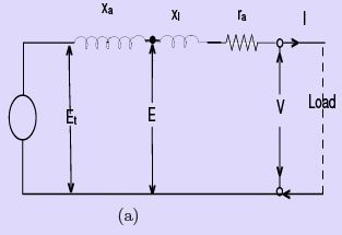
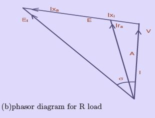
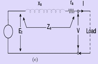
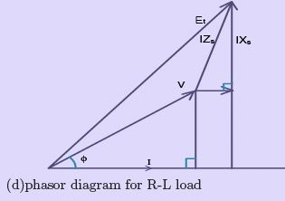
Figure 30: Equivalent circuits
A synchronous generator, under the assumption of a constant synchronous reactance, may be represented by an equivalent circuit per phase consisting of an ideal induced e.m.f. Et (proportional to the field excitation) in series with the armature resistance ra and the synchronous reactance Xs = Xl + Xa, where Xl is the leakage reactance and Xa is the fictitious reactance modelling armature reaction. This simple circuit (shown in Fig. 30) is sufficient to obtain the principal steady-state characteristics of a synchronous generator qualitatively and to derive useful relations for terminal voltage, current and power.
Generator Load Characteristics
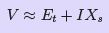
Consider a synchronous generator driven at constant speed with constant field excitation. On open circuit the terminal voltage V equals the induced e.m.f. Et. When a load is connected, the load current I produces a voltage drop across the synchronous impedance, and the terminal voltage is reduced. For the phasor relation we write:
V + Zs I = Et (24)
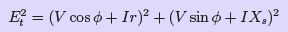
Algebraically, for loads where the resistance is small compared with reactance, the relation for non-reactive loads can be simplified (see Fig. 31 for phasor diagrams of different load types).
(25)
Since armature resistance is generally small relative to the synchronous reactance:
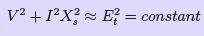
(26)
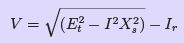
The locus of terminal voltage V as the load current varies (the V/I curve) is nearly an ellipse with semi-axes Et and the short-circuit current Isc. The short-circuit current Isc is the current that flows when the external load resistance is reduced to zero so that V = 0; under this condition
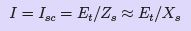
(27)
For a lagging load of zero power factor (purely inductive load) the phasor diagram is as in Fig. 31 and, neglecting armature resistance, the terminal voltage is approximately
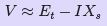
(28)
Figures 31 and 32 show typical variations of terminal voltage with load for different power factors. A leading load of zero power factor (purely capacitive) gives
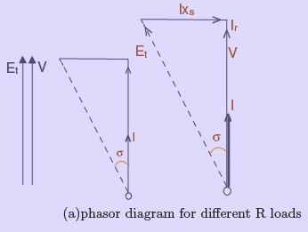
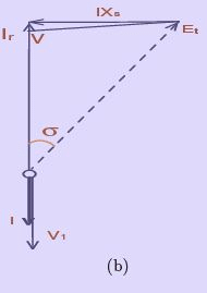
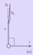
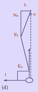
Figure 31: Variation of voltage with load at constant excitation
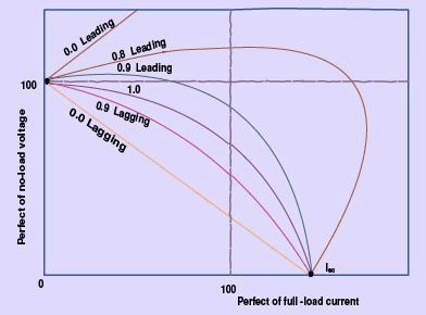
Figure 32: Generator load characteristics
and the corresponding approximate relation is
(29)
Because leading (capacitive) currents have a direct magnetizing effect on the main flux, the terminal voltage can increase with load for certain leading power factors. Intermediate power factors give intermediate loci (as in Fig. 32). The short-circuit current at which the terminal voltage falls to zero may be as high as about 1.5 per unit in large machines.
Generator Voltage-Regulation
The voltage-regulation of a synchronous generator is the change in terminal voltage when the load is suddenly removed while field excitation and speed remain constant. Numerically it is the difference between the induced e.m.f. Et (open-circuit value for the same field excitation) and the loaded terminal voltage V, expressed per unit of V:
ε = (Et - V) / V per unit (30)
Regulation depends strongly on load power factor. For unity and lagging power factors there is a voltage drop with increasing load (positive regulation). For a certain leading power factor the full-load regulation becomes zero (terminal voltage unchanged from no-load), and for still more leading power factors the regulation becomes negative (terminal voltage rises with load). From the phasor relation in Fig. 30, regulation for a load current I at power factor angle φ is obtained from:
(31)
This expression allows the regulation to be computed when Et and V are known or can be found from the phasor diagram.
Generator Excitation for Constant Voltage
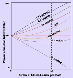
Figure 33: Generator Excitation for constant Voltage
Because the induced e.m.f. Et is proportional to the field excitation (when saturation is neglected and synchronous reactance is assumed constant), equation (31) can be used directly to determine the field excitation required to maintain a constant terminal voltage under varying load. Unity and lagging power-factor loads require increased excitation as load increases. Low leading power factors require reduced excitation because leading currents provide a direct magnetizing effect. Figure 33 shows typical field excitation versus armature current curves needed to hold the terminal voltage constant; ordinates are percentages of the no-load field excitation (neglecting saturation).
Generator Input and Output
Per phase, the real output delivered to a load is
P = V I cos φ
The electrical power converted from mechanical input (the air-gap power developed by the machine) per phase can be written in terms of the internal phasors (see Fig. 30). If the phasor Et is resolved along the direction of the armature current I we obtain:
(32)

(33)
Thus the electrical input equals the useful output plus the I2R copper loss in the armature. The prime mover must also supply rotational losses (friction and windage) and core losses, which do not appear explicitly in the phasor diagram.
In large machines armature resistance is small compared with synchronous reactance so that the synchronous impedance angle θ ≈ 90°. In this case:
(34)
and hence:

(35)
These relations show that the power developed by a synchronous machine with given values of Et, V and Zs is proportional to sin σ, and for small angles approximately proportional to σ. The angle σ (the power or torque angle) represents the displacement between the rotor magnetic axis and the resultant pole axes and is proportional to load power. Greater field excitation (larger Et) increases the developed power for a given angle σ, improving steady-state stability.
Salient Pole Rotor Machine
The synchronous reactance model Xs = Xa + Xl (where Xa represents armature reaction and Xl leakage) works well for cylindrical-rotor machines because the armature and main field m.m.f.s act on essentially the same magnetic circuit and the flux distribution is similar. For salient-pole machines the armature reaction produces different effects along two distinct axes (direct and quadrature), so the single synchronous reactance model is not adequate for precise prediction of performance.
Theory of Salient-pole Machines (Blondel's Two-reaction Theory)
In a salient-pole synchronous machine the armature reaction m.m.f. may be resolved into two orthogonal components: a direct-axis component Fad that acts on the same magnetic path as the main field (pole axis), and a quadrature-axis component Faq that acts across the interpolar or neutral region. These two components encounter different magnetic reluctances and therefore produce different magnetic effects and different effective reactances.
Blondel's two-reaction theory treats these effects separately by assigning to each component an armature-reaction reactance, respectively xad and xaq. The true leakage reactance xl and armature resistance may be included with either component (if approximately the same for both axes) or treated separately. The combined synchronous reactances along the direct and quadrature axes are:
(36)
Typically xaq (quadrature-axis reactance) is smaller than xad (direct-axis reactance) because the quadrature flux path contains larger interpolar air gaps and higher reluctance.
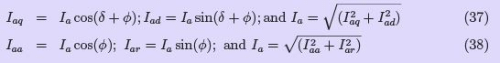
It is important to distinguish the direct- and quadrature-axis components of armature current (Iad, Iaq) from the active and reactive components of current (Iar, Iaa). Although both pairs are orthogonal, the former pair are referred to the induced e.m.f. Et (axis decomposition), while the latter pair are referred to the terminal voltage V (power decomposition).
The phasor diagram for a salient-pole synchronous generator supplying a lagging power-factor load is shown in Fig. 34. The two reactance voltage components Iaq·xsq and Iad·xsd are in quadrature with their respective current components. The armature resistance drop Ia·Ra is taken in phase with the total armature current Ia.
Direct construction of the phasor diagram is not immediate because the power angle σ is unknown a priori; however a simple geometric construction (illustrated in Fig. 34(d)) allows determination of Et and σ when V, load power factor angle φ, and axis reactances xsd, xsq are known. The construction adds the resistance drop to the tip of the terminal voltage phasor, then draws quadrature reactance drops appropriate to the current components to obtain the induced e.m.f.

Power Relations in a Salient-Pole Synchronous Machine
Neglecting armature winding resistance, the real power output is
P = V · Ia · cos φ (41)
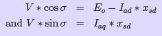
Using the phasor geometry of Fig. 34 and resolving phasors into direct and quadrature components, the power can be expressed in terms of the power (torque) angle σ. From the diagram:

(42)
Substituting these relations into the expression for power leads to

The resulting expression contains the usual sin σ term (as for a cylindrical-rotor machine) and an additional term proportional to sin 2σ. This extra term arises from the difference in reactances along the direct and quadrature axes and makes the power a little larger than that predicted by the cylindrical-rotor expression alone. The presence of the additional term also explains why a net e.m.f. and a reluctance torque can be produced even when the excitation is zero; this torque is due to variation of magnetic reluctance with rotor position and is known as the reluctance torque.
Experimental Determination of xd and xq
The unsaturated direct- and quadrature-axis synchronous reactances (xsd and xsq) of a three-phase synchronous machine can be determined experimentally by the slip test.
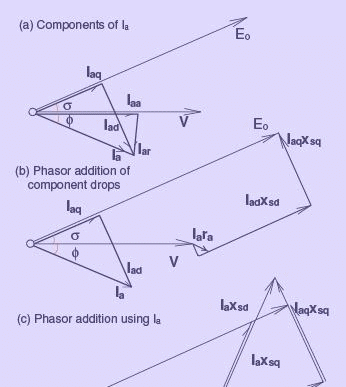
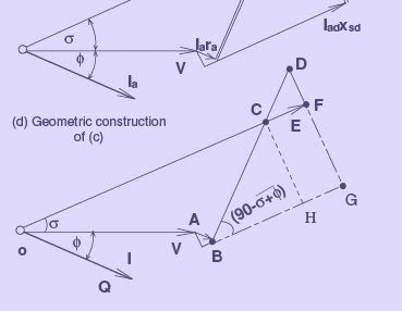
Figure 34: Phasor diagram of a generator - Two-reaction theory
In the slip test the rotor is driven close to but not exactly at synchronous speed (commonly using a d.c. motor) so that the rotor magnetic field rotates slightly with respect to the stator field. The field winding is kept open. The armature is supplied from a low voltage three-phase source through a variac. As the rotor position relative to the stator rotates, the synchronously rotating armature m.m.f. samples magnetic paths of varying reluctance, and the armature current cycles between a minimum and a maximum value.
The applied voltage divided by the minimum armature current gives the direct-axis synchronous reactance xsd (usually equal to the synchronous reactance obtained from conventional open-circuit and short-circuit tests), and the applied voltage divided by the maximum armature current gives the quadrature-axis reactance xsq. For higher accuracy the voltage and current oscillograms may be recorded and analysed.
Losses and Efficiency
To evaluate the efficiency of a synchronous generator it is necessary to establish the total losses under load. Principal losses are:
- Rotational losses such as friction and windage.
- Eddy-current and hysteresis losses in the magnetic circuit (core losses).
- Copper losses in the armature and field windings.
- Load or stray losses due to armature leakage flux producing additional eddy-current and hysteresis losses in surrounding iron.
Comments on determining these losses:
- Rotational losses (friction and windage) are approximately constant at synchronous speed and may be found from a no-load test.
- Core loss (eddy and hysteresis) can be determined by measuring the input power to an auxiliary motor driving the generator at no load with and without field excitation; the difference gives the core loss due to normal flux changes.
- Armature copper loss per phase is Ia2 Ra. Field winding loss is Vf If. For a multi-phase machine multiply the per-phase armature loss by the number of phases.
- Stray or load loss (additional iron and conductor losses caused by distorted flux under load) can be included by using an effective armature resistance larger than the measured d.c. resistance.
After all losses have been estimated, efficiency η is
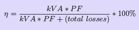
(44)
where the generator output (real power) is the apparent load kVA multiplied by the power factor (PF). Thus, in general
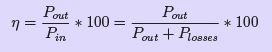
(45)
The input power Pin supplied by the prime mover equals the output power plus total losses: Pin = Pout + Plosses.
Summary: The cylindrical-rotor equivalent circuit with synchronous reactance provides a convenient first approximation for generator behaviour under load, but salient-pole machines require Blondel's two-reaction treatment to account for distinct direct- and quadrature-axis effects. Terminal voltage, regulation, excitation requirements and power output all depend on the interaction between induced e.m.f., synchronous reactance(s) and load power factor; losses determine the practical efficiency of the machine.
FAQs on Synchronous Generator Operation - 1
| 1. What is a synchronous generator and how does it operate? |  |
| 2. What are the main components of a synchronous generator? | |
| 3. What is the difference between a synchronous generator and an induction generator? | |
| 4. How is the output voltage of a synchronous generator regulated? | |
| 5. What are the advantages of using a synchronous generator? | |


 | Explore Courses for Electrical Engineering (EE) exam |
 | Get EduRev Notes directly in your Google search |