Inverting Operational Amplifier - Electronics and Experimental Methods, CSIR-NET Physical Sciences | Physics for IIT JAM, UGC - NET, CSIR NET PDF Download

Inverting Operational Amplifier
The Inverting Operational Amplifier configuration is one of the simplest and most commonly used op-amp topologies
The Open Loop Gain, ( Avo ) of an operational amplifier can be very high, as much as 1,000,000 (120dB) or more.
However, this very high gain is of no real use to us as it makes the amplifier both unstable and hard to control as the smallest of input signals, just a few micro-volts, (μV) would be enough to cause the output voltage to saturate and swing towards one or the other of the voltage supply rails losing complete control of the output.
As the open loop DC gain of an operational amplifier is extremely high we can therefore afford to lose some of this high gain by connecting a suitable resistor across the amplifier from the output terminal back to the inverting input terminal to both reduce and control the overall gain of the amplifier. This then produces and effect known commonly as Negative Feedback, and thus produces a very stable Operational Amplifier based system.
Negative Feedback is the process of “feeding back” a fraction of the output signal back to the input, but to make the feedback negative, we must feed it back to the negative or “inverting input” terminal of the op-amp using an external Feedback Resistor called Rƒ. This feedback connection between the output and the inverting input terminal forces the differential input voltage towards zero.
This effect produces a closed loop circuit to the amplifier resulting in the gain of the amplifier now being called its Closed-loop Gain. Then a closed-loop inverting amplifier uses negative feedback to accurately control the overall gain of the amplifier, but at a cost in the reduction of the amplifiers gain.
This negative feedback results in the inverting input terminal having a different signal on it than the actual input voltage as it will be the sum of the input voltage plus the negative feedback voltage giving it the label or term of a Summing Point. We must therefore separate the real input signal from the inverting input by using an Input Resistor, Rin.
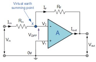
As we are not using the positive non-inverting input this is connected to a common ground or zero voltage terminal as shown below, but the effect of this closed loop feedback circuit results in the voltage potential at the inverting input being equal to that at the non-inverting input producing a Virtual Earth summing point because it will be at the same potential as the grounded reference input. In other words, the op-amp becomes a “differential amplifier”.
Inverting Operational Amplifier Configuration
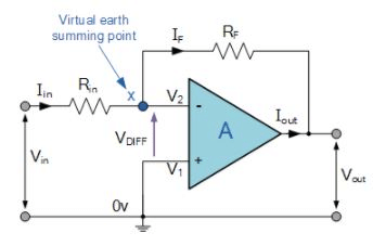
In this Inverting Amplifier circuit the operational amplifier is connected with feedback to produce a closed loop operation. When dealing with operational amplifiers there are two very important rules to remember about inverting amplifiers, these are: “No current flows into the input terminal” and that “V1 always equals V2”. However, in real world op-amp circuits both of these rules are slightly broken.
This is because the junction of the input and feedback signal ( X ) is at the same potential as the positive ( + ) input which is at zero volts or ground then, the junction is a “Virtual Earth”. Because of this virtual earth node the input resistance of the amplifier is equal to the value of the input resistor, Rin and the closed loop gain of the inverting amplifier can be set by the ratio of the two external resistors.
We said above that there are two very important rules to remember about Inverting Amplifiers or any operational amplifier for that matter and these are.
No Current Flows into the Input Terminals
The Differential Input Voltage is Zero as V1 = V2 = 0 (Virtual Earth)
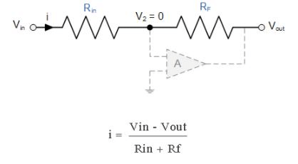
Then by using these two rules we can derive the equation for calculating the closed-loop gain of an inverting amplifier, using first principles.
Current ( i ) flows through the resistor network as shown.
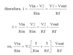
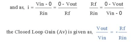
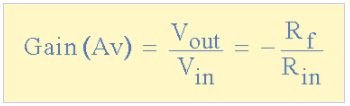
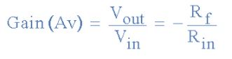
Then, the Closed-Loop Voltage Gain of an Inverting Amplifier is given as.
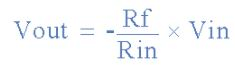
and this can be transposed to give Vout as:
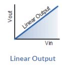
Linear Output
The negative sign in the equation indicates an inversion of the output signal with respect to the input as it is 180o out of phase. This is due to the feedback being negative in value.
The equation for the output voltage Vout also shows that the circuit is linear in nature for a fixed amplifier gain as Vout = Vin x Gain. This property can be very useful for converting a smaller sensor signal to a much larger voltage.
Another useful application of an inverting amplifier is that of a “transresistance amplifier” circuit. A Transresistance Amplifier also known as a “transimpedance amplifier”, is basically a current-to-voltage converter (Current “in” and Voltage “out”). They can be used in low-power applications to convert a very small current generated by a photo-diode or photo-detecting device etc, into a usable output voltage which is proportional to the input current as shown.
Transresistance Amplifier Circuit
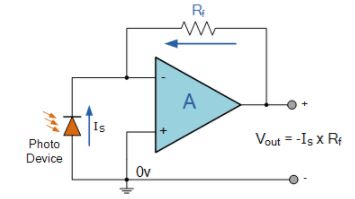
The simple light-activated circuit above, converts a current generated by the photo-diode into a voltage. The feedback resistor Rƒ sets the operating voltage point at the inverting input and controls the amount of output. The output voltage is given as Vout = Is x Rƒ. Therefore, the output voltage is proportional to the amount of input current generated by the photo-diode.
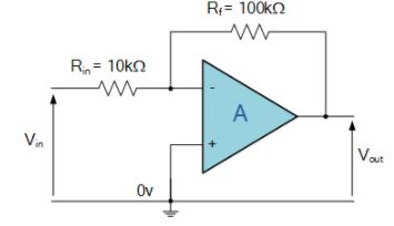
Inverting Op-amp Example No1
Find the closed loop gain of the following inverting amplifier circuit.
Using the previously found formula for the gain of the circuit
we can now substitute the values of the resistors in the circuit as follows,
Rin = 10kΩ and Rƒ = 100kΩ
and the gain of the circuit is calculated as: -Rƒ/Rin = 100k/10k = -10
Therefore, the closed loop gain of the inverting amplifier circuit above is given -10 or 20dB (20log(10)).
Inverting Op-amp Example No2
The gain of the original circuit is to be increased to 40 (32dB), find the new values of the resistors required.
Assuming that the input resistor is to remain at the same value of 10KΩ, then by re-arranging the closed loop voltage gain formula we can find the new value required for the feedback resistor Rƒ.
Gain = Rƒ/Rin
therefore, Rƒ = Gain x Rin
Rƒ = 40 x 10,000
Rƒ = 400,000 or 400KΩ
The new values of resistors required for the circuit to have a gain of 40 would be:
Rin = 10KΩ and Rƒ = 400KΩ
The formula could also be rearranged to give a new value of Rin, keeping the same value of Rƒ.
One final point to note about the Inverting Amplifier configuration for an operational amplifier, if the two resistors are of equal value, Rin = Rƒ then the gain of the amplifier will be -1 producing a complementary form of the input voltage at its output as Vout = -Vin. This type of inverting amplifier configuration is generally called a Unity Gain Inverter of simply an Inverting Buffer.
FAQs on Inverting Operational Amplifier - Electronics and Experimental Methods, CSIR-NET Physical Sciences - Physics for IIT JAM, UGC - NET, CSIR NET
| 1. What is an operational amplifier (op-amp)? |  |
| 2. How does an inverting operational amplifier work? | |
| 3. What is the gain of an inverting operational amplifier? | |
| 4. What are the advantages of using an inverting operational amplifier? | |
| 5. What are some applications of inverting operational amplifiers? | |


video lectures
,CSIR NET
,Important questions
,Inverting Operational Amplifier - Electronics and Experimental Methods
,Exam
,Inverting Operational Amplifier - Electronics and Experimental Methods
,UGC - NET
,Inverting Operational Amplifier - Electronics and Experimental Methods
,CSIR-NET Physical Sciences | Physics for IIT JAM
,practice quizzes
,Free
,shortcuts and tricks
,past year papers
,Extra Questions
,mock tests for examination
,CSIR-NET Physical Sciences | Physics for IIT JAM
,ppt
,Objective type Questions
,Summary
,MCQs
,CSIR NET
,Previous Year Questions with Solutions
,Semester Notes
,Sample Paper
,CSIR-NET Physical Sciences | Physics for IIT JAM
,study material
,Viva Questions
,CSIR NET
,UGC - NET
,UGC - NET
;


Inverting Operational Amplifier - Electronics and Experimental Methods, CSIR-NET Physical Sciences Free PDF Download
Importance of Inverting Operational Amplifier - Electronics and Experimental Methods, CSIR-NET Physical Sciences
Inverting Operational Amplifier - Electronics and Experimental Methods, CSIR-NET Physical Sciences Notes
Inverting Operational Amplifier - Electronics and Experimental Methods, CSIR-NET Physical Sciences Physics Questions
Study Inverting Operational Amplifier - Electronics and Experimental Methods, CSIR-NET Physical Sciences on the App
|
© EduRev
|
Education Revolution
|


|


