Non-Inverting Operational Amplifier - Electronics & Experimental Methods, CSIR-NET Physical Sciences | Physics for IIT JAM, UGC - NET, CSIR NET PDF Download

Non-Inverting Operational Amplifier
The second basic configuration of an operational amplifier circuit is that of a Non-inverting Operational Amplifier design.
In this configuration, the input voltage signal, ( VIN ) is applied directly to the non-inverting ( + ) input terminal which means that the output gain of the amplifier becomes “Positive” in value in contrast to the “Inverting Amplifier” circuit we saw in the last tutorial whose output gain is negative in value. The result of this is that the output signal is “in-phase” with the input signal.
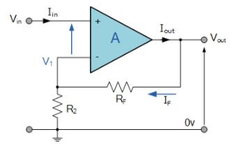
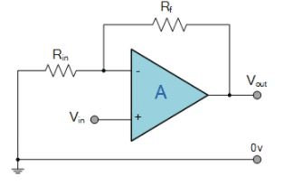
Feedback control of the non-inverting operational amplifier is achieved by applying a small part of the output voltage signal back to the inverting ( – ) input terminal via a Rƒ – R2 voltage divider network, again producing negative feedback. This closed-loop configuration produces a non-inverting amplifier circuit with very good stability, a very high input impedance, Rin approaching infinity, as no current flows into the positive input terminal, (ideal conditions) and a low output impedance, Rout as shown below.
Non-inverting Operational Amplifier Configuration
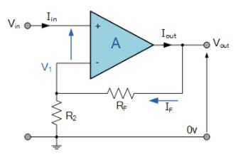
In the previous Inverting Amplifier tutorial, we said that for an ideal op-amp “No current flows into the input terminal” of the amplifier and that “V1 always equals V2”. This was because the junction of the input and feedback signal ( V1 ) are at the same potential.
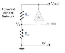
In other words the junction is a “virtual earth” summing point. Because of this virtual earth node the resistors, Rƒ and R2 form a simple potential divider network across the non-inverting amplifier with the voltage gain of the circuit being determined by the ratios of R2 and Rƒ as shown below.
Equivalent Potential Divider Network
Then using the formula to calculate the output voltage of a potential divider network, we can calculate the closed-loop voltage gain ( AV ) of the Non-inverting Amplifier as follows:
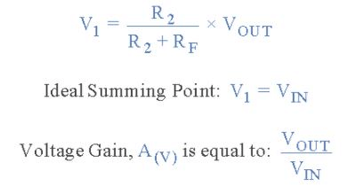
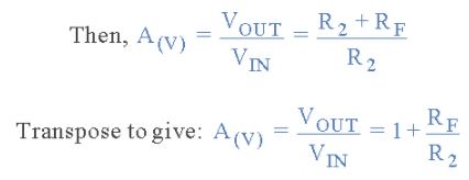
Then the closed loop voltage gain of a Non-inverting Operational Amplifier will be given as:
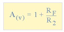
We can see from the equation above, that the overall closed-loop gain of a non-inverting amplifier will always be greater but never less than one (unity), it is positive in nature and is determined by the ratio of the values of Rƒ and R2.
If the value of the feedback resistor Rƒ is zero, the gain of the amplifier will be exactly equal to one (unity). If resistor R2 is zero the gain will approach infinity, but in practice it will be limited to the operational amplifiers open-loop differential gain, ( AO ).
We can easily convert an inverting operational amplifier configuration into a non-inverting amplifier configuration by simply changing the input connections as shown.
Voltage Follower (Unity Gain Buffer)
If we made the feedback resistor, Rƒ equal to zero, (Rƒ = 0), and resistor R2 equal to infinity, (R2 = ∞), then the circuit would have a fixed gain of “1” as all the output voltage would be present on the inverting input terminal (negative feedback). This would then produce a special type of the non-inverting amplifier circuit called a Voltage Follower or also called a “unity gain buffer”.
As the input signal is connected directly to the non-inverting input of the amplifier the output signal is not inverted resulting in the output voltage being equal to the input voltage, Vout = Vin. This then makes the voltage follower circuit ideal as a Unity Gain Buffer circuit because of its isolation properties.
The advantage of the unity gain voltage follower is that it can be used when impedance matching or circuit isolation is more important than amplification as it maintains the signal voltage. The input impedance of the voltage follower circuit is very high, typically above 1MΩ as it is equal to that of the operational amplifiers input resistance times its gain ( Rin x AO ). Also its output impedance is very low since an ideal op-amp condition is assumed.
Non-inverting Voltage Follower
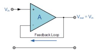
In this non-inverting circuit configuration, the input impedance Rin has increased to infinity and the feedback impedance Rƒ reduced to zero. The output is connected directly back to the negative inverting input so the feedback is 100% and Vin is exactly equal to Vout giving it a fixed gain of 1 or unity. As the input voltage Vin is applied to the non-inverting input the gain of the amplifier is given as:
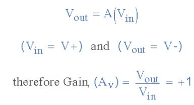
Since no current flows into the non-inverting input terminal the input impedance is infinite (ideal op-amp) and also no current flows through the feedback loop so any value of resistance may be placed in the feedback loop without affecting the characteristics of the circuit as no voltage is dissipated across it, zero current flows, zero voltage drop, zero power loss.
As the input current is zero giving zero input power, the voltage follower can provide a large power gain. However in most real unity gain buffer circuits a low value (typically 1kΩ) resistor is required to reduce any offset input leakage currents, and also if the operational amplifier is of a current feedback type.
The voltage follower or unity gain buffer is a special and very useful type of Non-inverting amplifier circuit that is commonly used in electronics to isolated circuits from each other especially in High-order state variable or Sallen-Key type active filters to separate one filter stage from the other. Typical digital buffer IC’s available are the 74LS125 Quad 3-state buffer or the more common 74LS244 Octal buffer.
One final thought, the closed loop voltage gain of a voltage follower circuit is “1” or Unity. The open loop voltage gain of an operational amplifier with no feedback is Infinite. Then by carefully selecting the feedback components we can control the amount of gain produced by a non-inverting operational amplifier anywhere from one to infinity.
Thus far we have analysed an inverting and non-inverting amplifier circuit that has just one input signal, Vin. In the next tutorial about Operational Amplifiers, we will examine the effect of the output voltage, Vout by connecting more inputs to the amplifier. This then produces another common type of operational amplifier circuit called a Summing Amplifier which can be used to “add” together the voltages present on its inputs.
FAQs on Non-Inverting Operational Amplifier - Electronics & Experimental Methods, CSIR-NET Physical Sciences - Physics for IIT JAM, UGC - NET, CSIR NET
| 1. What is a non-inverting operational amplifier? |  |
| 2. How does a non-inverting operational amplifier work? | |
| 3. What are the advantages of using a non-inverting operational amplifier? | |
| 4. How can the gain of a non-inverting operational amplifier be calculated? | |
| 5. What are some applications of non-inverting operational amplifiers? | |


shortcuts and tricks
,Free
,Viva Questions
,past year papers
,study material
,Summary
,CSIR-NET Physical Sciences | Physics for IIT JAM
,UGC - NET
,Non-Inverting Operational Amplifier - Electronics & Experimental Methods
,Previous Year Questions with Solutions
,practice quizzes
,Non-Inverting Operational Amplifier - Electronics & Experimental Methods
,video lectures
,Sample Paper
,Semester Notes
,Extra Questions
,Non-Inverting Operational Amplifier - Electronics & Experimental Methods
,CSIR-NET Physical Sciences | Physics for IIT JAM
,mock tests for examination
,UGC - NET
,Objective type Questions
,Exam
,CSIR NET
,MCQs
,UGC - NET
,ppt
,CSIR NET
,CSIR NET
,Important questions
,CSIR-NET Physical Sciences | Physics for IIT JAM
;


Non-Inverting Operational Amplifier - Electronics & Experimental Methods, CSIR-NET Physical Sciences Free PDF Download
Importance of Non-Inverting Operational Amplifier - Electronics & Experimental Methods, CSIR-NET Physical Sciences
Non-Inverting Operational Amplifier - Electronics & Experimental Methods, CSIR-NET Physical Sciences Notes
Non-Inverting Operational Amplifier - Electronics & Experimental Methods, CSIR-NET Physical Sciences Physics Questions
Study Non-Inverting Operational Amplifier - Electronics & Experimental Methods, CSIR-NET Physical Sciences on the App
|
© EduRev
|
Education Revolution
|


|


