Irodov Solutions: Electric Capacitance Energy of an Electric Field | I. E. Irodov Solutions for Physics Class 11 & Class 12 - JEE PDF Download
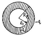
Q. 101. Find the capacitance of an isolated ball-shaped conductor of radius R1 surrounded by an adjacent concentric layer of dielectric with permittivity ε and outside radius R2.
Solution. 101. Let us mentally impart a charge q on the conductor, then
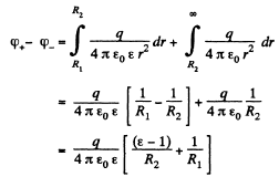
Hence the sought capacitance,

Q. 102. Two parallel-plate air capacitors, each of capacitance C, were connected in series to a battery with  Then one of the capacitors was filled up with uniform dielectric with permittivity ε. How many times did the electric field strength in that capacitor decrease? What amount of charge flows through the battery?
Solution. 102. From the symmetry o f the problem, the voltage across each capacitor,  and charge on each capacitor
  in the absence of dielectric.
Now when the dielectric is filled up in one of the capacitors, the equivalent capacitance of the system,

and the potential difference across the capacitor, which is filled with dielectric,

But φα E
So, as φ decreases  times, the field strength also decreases by the same factor and flow of charge

Q. 103. The space between the plates of a parallel-plate capacitor is filled consecutively with two dielectric layers 1 and 2 having the thicknesses d1 and d2 and the permittivities ε1 and ε2 respectively. The area of each plate is equal to S. Find:
(a) the capacitance of the capacitor;
(b) the density σ' of the bound charges on the boundary plane if the voltage across the capacitor equals V and the electric field is directed from layer 1 to layer 2.
Solution. 103. (a) As it is series combination of two capacitors,
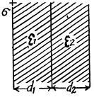

(b) Let, a be the initial surface charge density, then density of bound charge on the boundary plane.

But, 
So, 
Q. 104. The gap between the plates of a parallel-plate capacitor is filled with isotropic dielectric whose permittivity ε varies linearly from ε1 to ε2 (ε2 > ε1) in the direction perpendicular to the plates. The area of each plate equals S, the separation between the plates is equal to d. Find:
(a) the capacitance of the capacitor;
(b) the space density of the bound charges as a function of ε if the charge of the capacitor is q and the field E in it is directed toward the growing ε values.
Solution. 104. (a) We point the jt-axis lowards right and place the origin on the left hand side plate. The left plate is assumed to be positively charged.
Since e varies linearly, we can write,
ε(x) = a + bx
where a and b can be determined from the boundary condition. We have

Thus, 
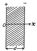
Now potential difference between the plates
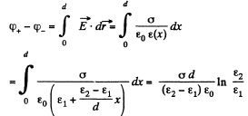
Hence, the sought capacitance 

and the space density of bound charges is

Q. 105. Find the capacitance of a spherical capacitor whose electrodes have radii R1 and R2 > R1 and which is filled with isotropic dielectric whose permittivity varies as ε = a/r, where a is a constant, and r is the distance from the centre of the capacitor.
Solution. 105. Let, us mentally impart a charge q to the conductor. Now potential difference between the plates,


Hence, the sought capacitance,

Q. 106. A cylindrical capacitor is filled with two cylindrical layers of dielectric with permittivities ε1 and ε2. The inside radii of the layers are equal to R1 and R2 > R1. The maximum permissible values of electric field strength are equal to E1m and E2m for these dielectrics. At what relationship between ε, R, and Em, will the voltage increase result in the field strength reaching the breakdown value for both dielectrics simultaneously?
Solution. 106. Let λ be the linear chaige density then,
 (1)
(1)
and,  (2)
(2)
The breakdown in either case will occur at the smaller value of r for a simultaneous breakdown of both dielectrics.
From (1) and (2)
 which & the sought relationship.
Q. 107. There is a double-layer cylindrical capacitor whose parameters are shown in Fig. 3.16. The breakdown field strength values for these dielectrics are equal to E1 and E2 respectively. What is the breakdown voltage of this capacitor if ε1R1E1< ε2R2E2?
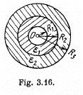
Solution. 107. Let, λ be the linear chaige density then, the sought potential difference,
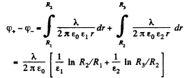


is the maximum acceptable value, and for values greater than  dielectric breakdown will take place,
Hence, the maximum potential difference between the plates,


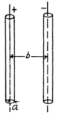
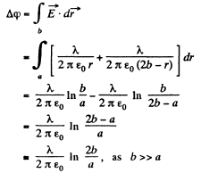
Q. 108. Two long straight wires with equal cross-sectional radii a are located parallel to each other in air. The distance between their axes equals b. Find the mutual capacitance of the wires per unit length under the condition b ≫ a.
Solution. 108. Let us suppose that linear chaige density of the wires be λ then, the potential difference,  The intensity of the electric field created by one of the wires at a distance x from its axis can be easily found with the help of the Gauss’s theorem,

Henee, capacitance, per unit length,

Q. 109. A long straight wire is located parallel to an infinite conducting plate. The wire cross-sectional radius is equal to a, the distance between the axis of the wire and the plane equals b. Find the mutual capacitance of this system per unit length of the wire under the condition a ≪ b.
Solution. 109. The field in the region between the conducting plane and the wire can bt obtained by using an oppositely charged wire as an image on the other side.
Then the potential difference between the wire and the plane,
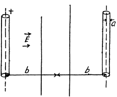
Hence, the sought mutual capacitance of the system per unit length of the wire 
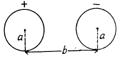
Q. 110. Find the capacitance of a system of two identical metal balls of radius a if the distance between their centres is equal to b, with b ≫ a. The system is located in a uniform dielectric with permittivity a.
Solution. 110. When b >> a, the charge distribution on each spherical conductor is practically unaffected by the presence of the other conductor. Then, the potential φ+ (φ-) on the positive (respectively negative) charged conductor is
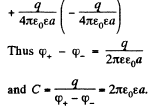
Note : if we require tetms which depend on a/b, we have to take account of distribution of charge on the conductors.
Q. 111. Determine the capacitance of a system consisting of a metal ball of radius a and an infinite conducting plane separated from the centre of the ball by the distance l if l ≫ a.
Solution. 111. As in Q.109 we apply the method of image. Then the potentical difference between the +vely charged sphere and the conducting plane is one half the nominal potential difference between the sphere and its image and is

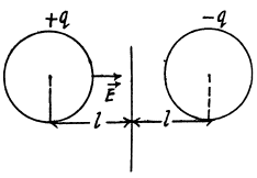
Thus

Q. 112. Find the capacitance of a system of identical capacitors between points A and B shown in (a) Fig. 3.17a; (b) Fig. 3.17b.
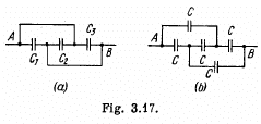
Solution. 112.

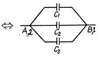
(a) 
The arrangement of capacitors shown in the problem is equivalent to the arrangement shown in the Fig.
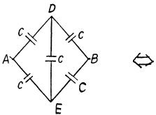
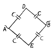
and hence the capacitance between A and B is,

(B) From the symmetry of the problem, there is no P.d. between D and E.. So, the combination reduces to a simple arrangement shown in the Fig and hence the net capacitance,

Q. 113. Four identical metal plates are located in air at equal distances d from one another. The area of each plate is equal to S. Find the capacitance of the system between points A and B if the plates are interconnected as shown (a) in Fig. 3.18a; (b) in Fig. 3.18b.

Solution. 113. (a) In the given arrangement, we have three capacitors of equal capacitance  and the first and third plates are at the same potential.
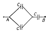
Hence, we can resolve the network into a simple form using series and parallel grouping of capacitors, as shown in the figure. Thus the equivalent capacitance

(b) Let us mentally impart the charges +q and -q to the plates 1 and 2 and then distribute them to other plates using charge conservation and electric induction. (Fig.). As the potential difference between the plates 1 and 2 is zero,

The potential difference between A and B,

Hence the sought capacitane,

Q. 114. A capacitor of capacitance C1 = 1.0 μ.F withstands the maximum voltage V1 = 6.0 kV while a capacitor of capacitance C2 = 2.0 μF, the maximum voltage V2 = 4.0 kV. What voltage will the system of these two capacitors withstand if they are connected in series?
Solution. 114. Amount of charge, that the capacitor of capacitance C1 can withstand, q1 = C1 V1 and similarly the charge, that the capacitor of capacitance C2 can withstand, q2 = C2 V2. But in series combination, charge on both the capacitors will be same, so, qmax, that the combination can withstand = C1V1,
as C1 V1 < C2 V2, from the numerical data, given.
Now, net capacitance of the system,

and hence, 
Q. 115. Find the potential difference between points A and B of the system shown in Fig. 3.19 if the emf is equal = 110 V and the capacitance ratio C2/C1 = η = 2.0.
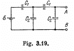
Solution. 115. Let us distribute the charges, as shown in the figure.
Now, we know that in a closed circuit, - Δφ = 0
So, in the loop, DCFED,
 (1)
(1)
Again in the loop DGHED,
 (2)
(2)
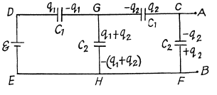
Using Eqs. (1) and (2), we get

Now, 
or, 
Q. 116. Find the capacitance of an infinite circuit formed by the repetition of the same link consisting of two identical capacitors, each with capacitance C (Fig. 3.20).

Solution. 116. The infinite circuit, may be reduced to the circuit, shown in the Fig. where, C0 is the net capacitance of the combination.

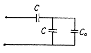
we get,
 taking only +ve value as C0 can not be negative.
Q. 117. A circuit has a section AB shown in Fig. 3.21. The emf of the source equals  the capacitor capacitances are equal to C1 = 1.0 μF and C2 = 2.0 μF, and the potential difference φA - φB = 5.0 V. Find the voltage across each capacitor.

Solution. 117. Let, us make the charge distribution, as shown in the figure.


Hence, voltage across the capacitor C1

and voltage across the capacitor, C2

Q. 118. In a circuit shown in Fig. 3.22 find the potential difference between the left and right plates of each capacitor.

Solution. 118.  then using
  in the closed circuit, (Fig.)

or, 
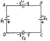
Hence the P.D. accross the left and right plates of capacitors,

and similarly

Q. 119. Find the charge of each capacitor in the circuit shown in Fig. 3.22.

Solution. 119. Taking benefit of tBe foregoing problem, the amount of charge on each capacitor

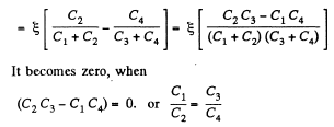
Q. 120. Determine the potential difference φA - φB between points A and B of the circuit shown in Fig. 3.23. Under what condition is it equal to zero?
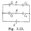
Solution. 120. Make the charge distribution, as shown in the figure. In the circuit, 12561.
-Δφ = 0 yields

and in the circuit 13461,

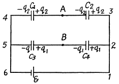
Now 
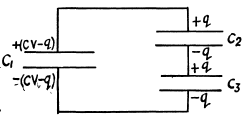
Q. 121. A capacitor of capacitance C1 = 1.0 μF charged up to a voltage V = 110 V is connected in parallel to the terminals of a circuit consisting of two uncharged capacitors connected in series and possessing the capacitances C2 = 2.0 μF and C3 = 3.0 μR. What charge will flow through the connecting wires?
Solution. 121. Let, the charge q flows through the connecting wires, then at the state of equilibrium, charge distribution will be as shown in the Fig. In the closed circuit 12341, using


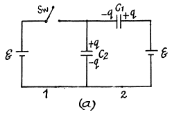
Q. 122. What charges will flow after the shorting of the switch Sw in the circuit illustrated in Fig. 3.24 through sections 1 and 2 in the directions indicated by the arrows?

Solution. 122. Initially, charge on the capacitor C1 or C2,
 as they are in series combination (Fig.-a)
when the switch is closed, in the circuit CDEFC from - Δφ = 0, /(Fig. b)
 (1)
(1)
And in the closed loop BCFAB from - Δφ = 0
 (2)
(2)
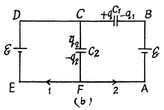
From (1) and (2) q1 - 0
Now, charge flown through section 
and charge flown through section 
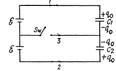
Q. 123. In the circuit shown in Fig. 3.25 the emf of each battery is equal to  and the capacitor capacitances are equal to C1 = 2.0 μF and C2 = 3.0 μF. Find the charges which will flow after the shorting of the switch Sw through sections' 1, 2 and 3 in the directions indicated by the arrows.

Solution. 123. When the switch is open, (Fig-a)

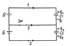
and when the switch is closed,

Hence, the flow of charge, due to the shortening of switch,
through section 
through the section 
and through the section 
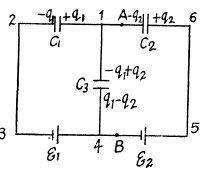
Q. 124. Find the potential difference φA — φB between points A and B of the circuit shown in Fig. 3.26.

Solution. 124. First of all, make the charge distribution, as shown in the figure.
In the loop 12341, using - Δφ = 0
 (1)
(1)
Similarly, in the loop 61456, using - Δφ = 0
 (2)
(2)
From Eqs. (1) and (2) we have

Hence, 
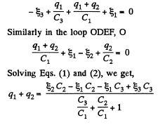
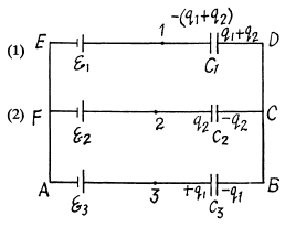
Q. 125. Determine the potential at point 1 of the circuit shown in Fig. 3.27, assuming the potential at the point O to be equal to zero. Using the symmetry of the formula obtained, write the expressions for the potentials. at points 2 and 3.
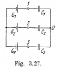
Solution. 125. In the loop ABDEA, using - Δφ = 0


And using the symmetry 
and 
The answers have wrong sign in the book.
Q. 126. Find the capacitance of the circuit shown in Fig. 3.28 between points A and B.
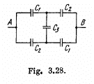
Solution. 126. Taking the advantage of symmetry of the problem charge distribution may be made, as shown in the figure.
In the loop, 12561, - Δφ = 0

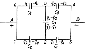
Now, capacitance of the network,
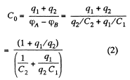
From Eqs. (1) and (2)

Q. 127. Determine the interaction energy of the point charges located at the corners of a square with the side a in the circuits shown in Fig. 3.29.
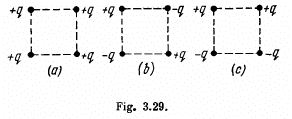
Solution. 127. (a) Interaction energy of any two point charges q1 and q2 is given by  is the separation between the charges.
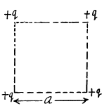
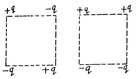
Hence, interaction energy of the system,

and 
Q. 128. There is an infinite straight chain of alternating charges q and -q. The distance between the neighbouring charges is equal to a. Find the interaction energy of each charge with all the others.
Instruction. Make use of the expansion of In (1 + α) in a power series in α.
Solution. 128. As the chain is of infinite length any two charge of same sign will occur symmetrically to any other charge of opposite sign.
So, interaction energy of each charge with all the others,
 (1)
(1)
But 
and putting  (2)
(2)
From Eqs. (1) and (2),

Q. 129. A point charge q is located at a distance l from an infinite tonducting plane. Find the interaction energy of that charge with chose induced on the plane.
Solution. 129. Using electrical im age method, interaction energy of the charge q with those induced on the plane.

Q. 130. Calculate the interaction energy of two balls whose charges qi and q, are spherically symmetrical. The distance between the centres of the balls is equal to l.
Instruction. Start with finding the interaction energy of a ball and a thin spherical layer.
Solution. 130. Consider the interaction energy of one of the balls (say 1) and thin spherical shell of the other. This interaction energy can be written as 


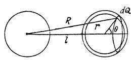
Hence finally integrating

Q. 131. A capacitor of capacitance C1 = 1.0 μF carrying initially a voltage V = 300 V is connected in parallel with an uncharged capacitor of capacitance C2 = 2.0 μF. Find the increment of the electric energy of this system by the moment equilibrium is reached. Explain the result obtained.
Solution. 131. Charge contained in the capacitor of capacitance C1 is q = C1 φ and the energy, stored in it :

Now, when the capacitors are connected in parallel, equivalent capacitance of the system,  and hence, energy stored in the system :
 as charge remains conserved during the process.
So, increment in the energy,

Q. 132. What amount of heat will be generated in the circuit shown in Fig. 3.30 after the switch Sw is shifted from position 1 to position 2?

Solution. 132. The charge on the condensers in position 1 are as shown. Here

and 
Hence, 
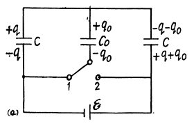
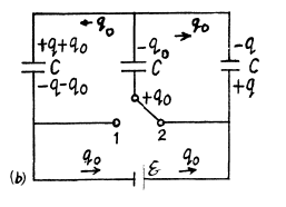
After the switch is thrown to position 2, the charges change as shown in (Fig-b).
A charge q0 has flown in the right loop through the two condensers and a charge q0 through the cell, Because of the symmetry of the problem there is no change in the energy stored in the condensers. Thus
H (Heat produced) = Energy delivered by the cell

Q. 133. What amount of heat will be generated in the circuit shown. in Fig. 3.31 after the switch Sw is shifted from position 1 to position 2?
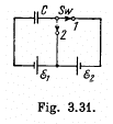
Solution. 133. Initially, the charge on the right plate of^the capacitor,  and finally, when switched to the position, 2. charge on the same plate of capacitor ;

So, 
Now, from eneigy conservation,
ΔU + Heat liberated = Acell where ΔU is the electrical energy.

as only the cell with e.m.f.  is responsible for redistribution of the charge. So,

Hence heat liberated 
Q. 134. A system consists of two thin concentric metal shells of radii R1 and R2 with corresponding charges q1 and q2. Find the selfenergy values W1 and W2 of each shell, the interaction energy of the shells W12, and the total electric energy of the system.
Solution. 134. Self energy of each shell is given by qφ/2 where φ is the potential of the shell, created only by the charge q, on it.
Hence, self energy of the shells 1 and 2 are :

The interaction energy between the charged shells equals charge q of one shell, multiplied by the potential φ, created by other shell, at the point of location of charge q.
So, 
Hence, total enegy of the system,

Q. 135. A charge q is distributed uniformly over the volume of a ball of radius R. Assuming the permittivity to be equal to unity, find:
(a) the electrostatic self-energy of the ball;
(b) the ratio of the energy W1 s tored in the ball to the energy W2 pervading the surrounding space.
Solution. 135. Electric fields inside and outside the sphere with the help of Gauss theorem :

Sought self energy of the ball


Hence,

Q. 136. A point charge q = 3.0 μC is located at the centre of a spherical layer of uniform isotropic dielectric with permittivity ε = 3.0. The inside radius of the layer is equal to a = 250 mm, the outside radius is b = 500 mm. Find the electrostatic energy inside the dielectric layer.
Solution. 136. (a) By the expression  , for a spherical layer.
To find the electrostatic energy inside the dielectric layer, we have to integrate the upper expression in the limit [a, b] 
Q. 137. A spherical shell of radius R1 with uniform charge q is expanded to a radius R2. Find the work performed by the electric forces in this process.
Solution. 137. As the field is conservative total work done by the field force,

Q. 138. A spherical shell of radius R1 with a uniform charge q has a point charge q0 at its centre. Find the work performed by the electric forces during the shell expansion from radius R1 to radius R2.
Solution. 138. Initially, energy of the system, Ui = W1 + W12 where, W1 is the self energy and W12 is the mutual energy.
So, 
and on expansion, energy of the system,

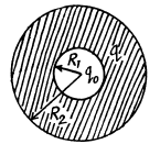
Now, work done by the field force, A equals the decrement in the electrical energy,

Alternate : The work of electric forces is equal to the decrease in electric energy ot the system,

In order to find the difference  we note that upon expansion of the shell, the electric field and hence the energy localized in it, changed only in the hatched spherical layer consequently (Fig.).

where E1 and E2 are the field intensities (in the hatched region at a distance r from the centre of the system) before and after the expansion of the shell. By using Gauss’ theorem, we find

As a result of integration, we obtain

Q. 139. A spherical shell is uniformly charged with the surface derisity σ. Using the energy conservation law, find the magnitude of the electric force acting on a unit area of the shell.
Solution. 139. Energy of the charged sphere of radius r, from the equation

If the radius of the shell changes by dr then work done is

Thus sought force per unit area,

Q. 140. A point charge q is located at the centre O of a spherical uncharged conducting layer provided with a small orifice (Fig. 3.32). The inside and outside radii of the layer are equal to a and b respectively. What amount of work has to be performed to slowly transfer the charge q from the point O through the orifice and into infinity?
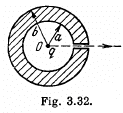
Solution. 140. Initially, there will be induced charges of magnitude - q and +q on the inner and outer surface of the spherical layer respectively. Hence, the total electrical energy of the system is the sum of self energies of spherical shells, having radii a and b, and their mutual energies including the point charge q.

or 
Finally, charge q is at infinity hence, Uf = 0
Now, work done by the agent = increment in the energy

Q. 141. Each plate of a parallel-plate air capacitor has an area S. What amount of work has to be performed to slowly increase the distance between the plates from x1 to x2 if
(a) the capacitance of the capacitor, which is equal to q, or
(b) the voltage across the capacitor, which is equal to V, is kept constant in the process?
Solution. 141. (a) Sought work is equivalent to the work performed against the electric field created by one plate, holding at rest and to bring the other plate away. Therefore the required work,

where  is the intensity of the field created by one plate at the location of other.
So, 
Alternate :  (as field is potential)

(b) When voltage is kept const., the force acing on each plate of capacitor will depend on the distance between the plates.
So, elementary work done by agent, in its displacement over a distance dx, relative to the other,

But, 
Hence, 
Alternate : From energy Conservation,

or 

So 
Q. 142. Inside a parallel-plate capacitor there is a plate parallel to the outer plates, whose thickness is equal to η = 0.60 of the gap width. When the plate is absent the capacitor capacitance equals c = 20 nF. First, the capacitor was connected in parallel to a constant voltage source producing V = 200 V, then it was disconnected from it, after which the plate was slowly removed from the gap. Find the work performed during the removal, if the plate is
(a) made of metal; (b) made of glass.
Solution. 142. (a) When metal plate of thickness ηd is inserted inside the capacitor, capacitance of the system becomes 
Now, initially, charge on the capacitor, 
Finally, capacitance of the capacitor, 
As the source is disconnected, charge on the plates will remain same during the process.
Now, from energy conservation,

or, 
Hence 
(b) Initially, capacitance of the system is given by,
 this is the cap acitance of two capacitors in series)
So, charge on the plate, 
Capacitance of the capacitor, after the glass plate has been removed equals C
From energy conservation,


Q. 143. A parallel-plate capacitor was lowered into water in a horizontal position, with water filling up the gap between the plates d = 1.0 mm wide. Then a constant voltage V = 500 V was applied to the capacitor. Find the water pressure increment in the gap.
Solution. 143. When the capactior which is immersed in water is connected to a constant voltage source, it gets charged. Suppose σ0 is the free charge density on the condenser plates. Because water is a dielectric, bound charges also appear in it Let σ' be the surface density of bound charges. (Because of homogeneity of the medium and uniformity of the field when we ignore edge effects no volume density of bound charges exists.) The electric field due to free charges only  that due to bound charges is
  and the total electric field is
  Recalling that the sign of bound charges is opposite o f the free charges, we have

Because of the field that exists due to the free charges (not the total field; the field due to the bound charges must be excluded for this purpose as they only give rise to self energy effects), there is a force attracting the bound charges to the near by plates. This force is

The factor 1/2 needs an explanation. Normally the force on a test charge is qE in an electric field E. But if the chaige itself is produced by the electric filed then the force must be constructed bit by bit and is

if 

This factor of 1/2 is well known. For exaipple the energy of a dipole of moment  in an electric field
  while the energy per unit volume o f a linear dielectric in an electric field is
  the polarization vector (i.e. dipole moment per unit volume). Now the force per unit area manifests ifself as excess pressure of the liquid.
Noting that 
We get 
Substitution, using ε = 81 for water, gives Δp = 7.17 k Pa = 0.07 atm.
Q. 144. A parallel-plate capacitor is located horizontally so that one of its plates is submerged into liquid while the other is over its surface (Fig. 3.33). The permittivity of the liquid is equal to ε, its density is equal to p. To what height will the level of the liquid in the capacitor rise after its plates get a charge of surface density σ?
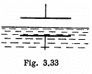
Solution. 144. One way of doing this problem will be exactly as in the previous case so let us try an alternative method based on energy. Suppose the liquid rises by a distance h. Then let us calculate the extra energy of the liquid as a sum of polarization energy and the ordinary gravitiational energy. The latter is

If σ is the free charge surface density on the plate, the bound charge density is, from the previous problem,

This is also the volume density of induced dipole moment i.e. Polarization. Then the energy is, as before

and the total polarization energy is


Then, total eneigy is

The actual height to which the liquid rises is determined from the formula

This gives 
Q. 145. A cylindrical layer of dielectric with permittivity ε is inserted into a cylindrical capacitor to fill up all the space between the electrodes. The mean radius of the electrodes equals R, the gap between them is equal to d, with d ≪ R. The constant voltage V is applied across the electrodes of the capacitor. Find the magnitude of the electric force pulling the dielectric into the capacitor.
Solution. 145. We know that energy of a capacitor 
Hence,  (1)
(1)
Now, since d << R, the capacitance of the given capacitor can be calculated by the formula of a parallel plate capacitor. Therefore, if the dielectric is introduced upto a depth x and the length of the capacitor is l, we have,
 (2)
(2)
From (1) and (2), we get,

Q. 146. A capacitor consists of two stationary plates shaped as a semi-circle of radius R and a movable plate made of dielectric with permittivity a and capable of rotating about an axis O between the stationary plates (Fig. 3.34). The thickness of the movable plate is equal to d which is practically the separation between the stationary plates. A potential difference V is applied to the capacitor. Find the magnitude of the moment of forces relative to the axis O acting on the movable plate in the position shown in the figure.
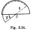
Solution. 146. When the capacitor is kept at a constant potential difference V, the work performed by the moment of electrostatic forces between the plates when the inner moveable plate is rotated by an angle dφ equals the increase in the potential energy of the system. This comes about because when charges are made, charges flow from the battery to keep the potential constant and the amount of the work done by these charges is twice in magnitude and opposite in sign to the change in the energy of the capacitor Thus 
Now the capacitor can be thought of as made up two parts (with and without the dielectric) in parallel.
Thus 
as the area of a sector of angle  Differentiation then gives

The negative sign of Nz indicates that the moment of the force is acting clockwise (i.e. trying to suck in the dielectric).
FAQs on Irodov Solutions: Electric Capacitance Energy of an Electric Field - I. E. Irodov Solutions for Physics Class 11 & Class 12 - JEE
| 1. How is the electric capacitance energy of an electric field defined? |  |
| 2. What is the formula to calculate the electric capacitance energy of an electric field? |  |
| 3. How does the electric capacitance energy of an electric field relate to the capacitance of the capacitor? |  |
| 4. Can the electric capacitance energy of an electric field be negative? |  |
| 5. How is the electric capacitance energy of an electric field useful in practical applications? |  |


