DC Pandey Solutions: Alternating Current | Physics Class 12 - NEET PDF Download

Introductory Exercise 25.1
Ques 1: An electric lamp which runs at 100 V dc and consumes 10 A current is connected to ac mains at 150 V, 50 Hz cycles with a choke coil in series. Calculate the inductance and drop of voltage across the choke. Neglect the resistance of choke.
Sol: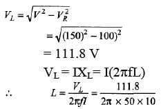
= 0.036 H
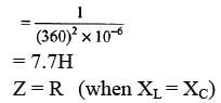
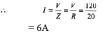
Ques 2: A circuit operating at  contains a 1μF capacitor and a 20Ωresistor. How large an inductor must be added in series to make the phase angle for the circuit zero? Calculate the current in the circuit if the applied voltage is 120 V.
Sol: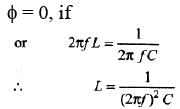
Introductory Exercise 25.2
Ques 1: If a 0.03 H inductor, a 10Ω resistor and a 2μF capacitor are connected in series. At what frequency will they resonate? What will be the phase angle at resonance?
Sol: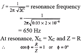
Ques 2: An arc lamp consumes 10 A at 40 V. Calculate the power factor when it is connected with a suitable value of choke coil required to run the arc lamp on ac mains of 200 V (rms) and 50 Hz.
Sol: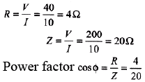
= 0.2
Exercises
For JEE Main
Subjective Questions
Ques 1: (a) What is the reactance of a 2.00 H inductor at a frequency of 50.0 Hz?
(b) What is the inductance of an inductor whose reactance is 2.00Ω at 50.0 Hz?
(c) What is the reactance of a 2.00 μF capacitor at a frequency of 50.0 Hz?
(d) What is the capacitance of a capacitor whose reactance is 2.00Ω at 50.0 Hz?
Sol: 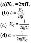
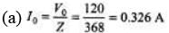
Ques 2: A 300 Ω resistor, a 0.250 H inductor, and a 8.00 μF capacitor are in series with an ac source with voltage amplitude 120 V and angular frequency 400 rad/s.
(a) What is the current amplitude?
(b) What is the phase angle of the source voltage with respect to the current? Does the source voltage lag or lead the current?
(c) What are the voltage amplitudes across the resistor, inductor, and capacitor?
Sol: XL = ωL = 100Ω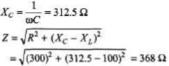
(b) Since XC > XL, voltage lags the current by an angle given by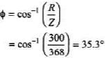
(c) (V0)R = I0R = (0.326) 300 = 97.8 V
(V0)L = I0XL = (0.326) (100) = 32.6 V
(V0)C = I0XC = (0.326) (312.5) = 102 V
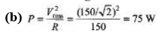
Ques 3: In an L-C-R series circuit, R = 150Ω, L = 0.750 H, and C = 0.0180 μF. The source has voltage amplitude V = 150 V and a frequency equal to the resonance frequency of the circuit.
(a) What is the power factor?
(b) What is the average power delivered by the source?
(c) The capacitor is replaced by one wit h C = 0.0360 μB and the source frequency is adjusted to the new resonance value. Then, what is the average power delivered by the source?
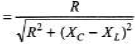
Sol: (a) At resonance frequency, XL= XC, Z = R and power factor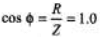
Ques 4: A series circuit has an impedance of 60.0 W and a power factor of 0.720 at 50.0 Hz. The source voltage lags the current.
(a) What circuit element, an inductor or a capacitor, should be placed in series with the circuit to raise its power factor?
(b) What size element will raise the power factor to unit y?
Sol: (a) Voltage lags
XC > XL
Power factor, 
To increase the power factor denominator should decrease.
Hence XL should increase. Therefore an inductor is required to be connected.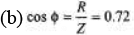
R = 0.72 Z = 0.72 × 60 = 43.2 Ω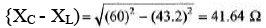
New inductor of inductance 41.64 Ω should be added in the circuit.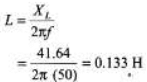
Ques 5: Voltage and current for a circuit with two elements in series are expressed as :
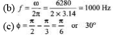
V(t) = 170sin (6280 t +π/3) volt
i(t) = 8.5sin(6280t + π/2)amp
(a) Plot the two waveforms.
(b) Determine the frequency in Hz.
(c) Determine the power factor stating its nature.
(d) What are the values of the elements?
Sol:
Power factor = cos Φ = cos 30°
= √3/2
From the given functions of V and i we can see that current function leads the voltage function.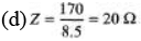 ...(i)
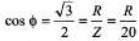
∴ 
= 10 Ω
= 15.92 × 10⁻⁶F
Ques 6: A 5.00 H inductor with negligible resistance is connected across an ac source. Voltage amplitude is kept constant at 60.0 V but whose frequency can be varied. Find the current amplitude when the angular, frequency is
(a) 100 rad/s (b) 1000 rad/s (c) 10000 rad/s
Sol: 
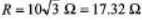
Ques 7: A 300Ω resistor is connected in series wit h a 0.800 H inductor. The voltage across the resistor as a function of time is VR = (2.50 V)cos [(950rad/s)t].
(a) Derive an expression for the circuit current.
(b) Determine the inductive reactance of the inductor.
(c) Derive an expression for the voltage VL across the inductor.
Sol: 
= 8.33 mA
Current function and VR function are in phase. Hence,
I = (8.33 mA) cos [(950 rad/s) t]
(b) XL= ωL = 950 × 0.8 = 760Ω
(c) (V0)L = I0XL = (8.33 × 10⁻³) (760)
= 6.33V
Now, VL function leads the current (or VR ) function by 90°.
FL = 6.33 cos(950t + 90°) = - 6.33 sin (950 t)
Ques 8: An L-C-R series circuit with L = 0.120 H, R = 240Ω, and C = 7.30 μF carries an rms current of 0.450 A with a frequency of 400 Hz.
(a) What are the phase angle and power factor for this circuit?
(b) What is the impedance of the circuit?
(c) What is the rms voltage of the source?
(d) What average power is delivered by the source?
(e) What is the average rate at which electrical energy is converted to thermal energy in the resistor?
(f) What is the average rate at which electrical energy is dissipated ( converted to other forms) in the capacitor?
(g) In the inductor?
Sol: XL=2π fL = 301Ω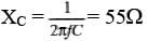
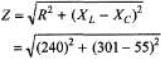
= 343Ω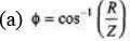

= 45.6°
= 240/343
= 0.699
Since XL > XC, voltage leads the current.
(b) Impedance = Z = 343Ω
(c) Vrms = Irms Z
= 0.45 × 343 = 155 V 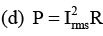
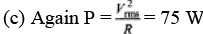
= (0.45)2 (240) = 48.6W
(e) P = PR= 48.6 W
(f) PC = 0
(g) PL = 0
|
74 videos|314 docs|88 tests
|
FAQs on DC Pandey Solutions: Alternating Current - Physics Class 12 - NEET
| 1. What is the difference between direct current and alternating current? |  |
| 2. How does alternating current work? | |
| 3. What is the frequency of alternating current? | |
| 4. How is the voltage of alternating current measured? | |
| 5. What are the advantages of alternating current over direct current? | |


past year papers
,DC Pandey Solutions: Alternating Current | Physics Class 12 - NEET
,Sample Paper
,Summary
,practice quizzes
,Previous Year Questions with Solutions
,shortcuts and tricks
,study material
,video lectures
,Important questions
,Semester Notes
,ppt
,Free
,MCQs
,DC Pandey Solutions: Alternating Current | Physics Class 12 - NEET
,Extra Questions
,mock tests for examination
,DC Pandey Solutions: Alternating Current | Physics Class 12 - NEET
,Objective type Questions
,Viva Questions
,Exam
;


DC Pandey Solutions: Alternating Current Free PDF Download
Importance of DC Pandey Solutions: Alternating Current
DC Pandey Solutions: Alternating Current Notes
DC Pandey Solutions: Alternating Current NEET Questions
Study DC Pandey Solutions: Alternating Current on the App
|
© EduRev
|
Education Revolution
|


|


within 7 days!