Class 12 Exam > Class 12 Notes > Types of Pulse Modulation
Types of Pulse Modulation - Class 12 PDF Download
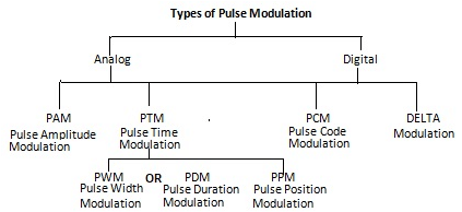
Pulse Modulation is divided into two as Analog and Digital.
Analog Modulation is divided into Pulse Amplitude Modulation, Pulse Time Modulation, Pulse Width Modulation or Pulse Duration Modulation and Pulse Position Modulation
Digital Modulation is divided into Pulse Code Modulation and Delta Modulation. All the Pulse Modulations are explained below with the help of diagram.The types of Pulse Modulation are shown in the Figure below

PULSE AMPLITUDE MODULATION (PAM):
PAM Generation :

PULSE AMPLITUDE MODULATION (PAM):
In pulse amplitude modulation (PAM), the information, signal is sampled at the sampling rate and the carrier pulse In pulse is discretely amplitude - modulated at the sampling frequency. For faithful transmission, the signal should It-119 The information is transferred to e sampled sufficiently. the pulse at the sampling frequency.
PAM is not often used because the amplitude of pulses not constant and goes against the basic advantage of NI is system. Therefore, in a practical PAM system, the pulses are made to perform frequency modulation of the carrier rather than amplitude modulation.
PAM Generation :
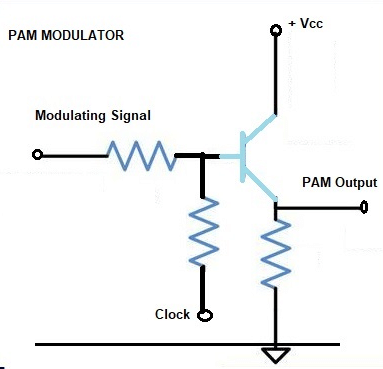
A PAM modulator circuit is shown in Figure. This circuit is a simple emitter follower. In the absence of clock signal, the output follows the input. The modulating signal is applied as the input signal. Another input to the base of the transistor is the clock signal. The frequency of the clock signal is made equal to the desired carrier pulse train frequency. The amplitude of the clock signal is so chosen that the high level is at ground (OV), and the low level is at some negative voltage which is sufficient to bring the transistor in the cut-off region. Thus when the clock signal is high, the circuit behaves as an emitter follower, and the output follows the input modulating signal. When the clock signal is low, the transistor is cut-off and the output is zero.
Thus the output waveform, shown in Figure is the desired PAM signal.
PAM Detection:
PAM Detection:
A PAM demodulator circuit is just an envelope detector followed by a low pass filter. The diode and R - C combination network act as the envelope detector. This is followed by a second order OP-AMP low pass filter (LPF) to have a good filtering characteristic. Thus, for the received PAM Signal as the input signal, the desired demodulated signal is show in figure is the output.


PULSE WIDTH MODULATION (PWM)
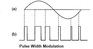
In this system, we have fixed amplitude and starting time of each pulse, but the width of each pulse is made proportional to the amplitude of the signal at that instant.


PWM Generation:
The clock signal of the desired frequency is applied flow which negative edge triggering pulses are derived with the help of a diode and a R1 – C1 combination which works as differentiator.
The clock signal of the desired frequency is applied flow which negative edge triggering pulses are derived with the help of a diode and a R1 – C1 combination which works as differentiator.
These negative trigger pulses applied to the pin 2 of IC 555, which is working as the monostable multivibrator makes an excellent voltage-to-time converter. These pulses decide the starting time of the PWM pulses. The end of pulses depends upon R2 - C2 combination on the modulating signal applied at pin 5.
The width of the pulses depends upon the value of the modulating signal and thus the pin 3 output is the desired PWM.
PDM uses in communication:
1. It is often used in the high powered audio amplifiers used to modulate AM transmitters.
2. It has also been used for telemetry systems.
3. Though still an analog mode, it is more robust than PAM because it is insensitive to amplitude changes due to noise and distortion.
4. PWM still works if synchronization between transmitter and receiver fails.
Disadvantages of PDM :
1. PDM pulses are of varying width and therefore of varying power content.
| PWM Modulator |
PULSE POSITION MODULATION (PPM)
Generation and demodulation of PPM
The Pulse position modulation obtained from PWM as shown in Figure in PWM, it is seen that each pulse has a leading edge and a trailing edge. Their position depends on pulse width, which is determined by the signal amplitude at the instant. In order to it obtain the PPM signal what is required is first a PWM signal and removal of the leading edges of PWM pulses.
In demodulation of PPM, it is first converted into PWM, this is done with a flip-flop or bistable multivibrator. One input of the multivibrator get trigger pulses from a local generator which is synchronized by trigger pulses gets from the transmitter, in addition to these triggers are utilized to switch off one of the stages of the flip-flop. The PPM pulse are fed to the other base of the flip-flop and switch that stage ON (actually by switching the other one OFF). The resulting PWM pulse train is then demodulated.
The PWM signal is applied to pin no.2 through the diode R1 - C1 combination. Thus the input to pin no.2 is the negative trigger pulse which corresponds o the trailing edges of PWM wave form. The IC 555 timer is working in a monostable mode and the width of the pulse is constant (governed by R2 - C2 combination).
The negative trigger pulses decide the starting time of the output pulses and thus the output at Pin no.3 is the desired pulse position modulated (PPM) signal.
PULSE CODE MODULATION (PCM) :
PCM is the mainly used digital modulation system. In PCM the accessible range of signal voltages, separated into levels, and each is given a binary number. Every sample is then symbolized by the binary number representing the level adjoining to its amplitude, and this number is conveyed in serial form. In linear PCM, levels are separated by equal voltage gradations.
The number of levels available depends on the number bits used to express the sample value. The number of levels is given by
N = 2m
Here N is the number of levels, and
m is the number of bits per sample
Problem: Estimate the number of levels if the number of bits per sample is as follows.
(a) 8 (as in telephony)
(b) 16 (as in compact disc audio systems)
Solution :
a) The number of levels with 8 bits per sample
N = 2m = 28 = 256
b) The number of levels with 16 bits per sample N = 2m = 216 = 65,536.
This process is called 'quantizing'.
For example, if the signal amplitude is 3.2 volts at one instant it will be sent as a digit 3 only but as 3.2 volts pulse. As there are 8 levels (23) as taken in this example the bits required to transmit the levels are 3. The digit 3 will be sent as 011. That is, OPP. Where O represents no pulse and represent pulse. However, if we take yet another level 5 volts the binary digit is 101, POP this will be sent as 101 or POP. This makes the demodulation of the signal easier.
Generation of PCM Signals :
In short in the pulse code modulation process: the signal is continuously sampled. It is quantized, coded and then transmitted. Quantizing is done to the nearest standard amplitude. The code is binary number when sufficient quantizing levels are used the signal will resemble the same as is from an analog system.
A group of pulses representing a sample is termed a word. The word consists of a supervisory or signalling bit and the binary bits. So a sample is expressed by n + 1 bits where 2n is the chosen number of standard levels.
Demodulation of PCM:
The PCM signal is given to a quantizer. This stage eliminates the noise and requantizes the signal. The output of quantizer is given to a decoder. The decoder is a Digital to Analog converter. It performs the reverse operation of the encoder. The PAM signal is reconstituted. A filter is used to reject the unwanted frequency components. The output of the filter will be the original signal.
Advantages of PCM:
1. PCM is immune to noise and interference.
2. It is easy to generate PCM signals.
Disadvantages of PCM :
1. PCM requires very complex circuitry.
2. PCM requires large band width compared to analog signal.
Applications of PCM:
1. It is used for telephony.
2. It is used in data transmission.
3. It is used in space communications.
FAQs on Types of Pulse Modulation - Class 12
| 1. What are the different types of pulse modulation? |  |
Ans. The different types of pulse modulation are Pulse Amplitude Modulation (PAM), Pulse Width Modulation (PWM), and Pulse Position Modulation (PPM). These techniques are used to encode analog signals into digital pulse signals for transmission or storage.
| 2. How does Pulse Amplitude Modulation (PAM) work? |  |
Ans. Pulse Amplitude Modulation (PAM) is a type of pulse modulation where the amplitude of the pulses is varied in proportion to the instantaneous amplitude of the analog signal being transmitted. This modulation technique is commonly used in digital communication systems to transmit analog signals over a digital channel.
| 3. What is the principle behind Pulse Width Modulation (PWM)? |  |
Ans. Pulse Width Modulation (PWM) is a type of pulse modulation where the width of the pulses is varied in proportion to the amplitude of the analog signal being transmitted. The principle behind PWM is to encode the analog signal by varying the duration of high and low states of the pulses. PWM is widely used in applications such as motor speed control, power converters, and audio amplifiers.
| 4. How does Pulse Position Modulation (PPM) differ from other pulse modulation techniques? |  |
Ans. Pulse Position Modulation (PPM) is a type of pulse modulation where the position of the pulses is varied according to the instantaneous amplitude of the analog signal being transmitted. Unlike PAM and PWM, which vary the amplitude or width of the pulses, PPM encodes information by shifting the position of the pulses. This technique is commonly used in applications where timing accuracy is critical, such as radar systems and optical communication.
| 5. What are the advantages of pulse modulation techniques? |  |
Ans. Pulse modulation techniques offer several advantages, including efficient use of bandwidth, immunity to noise and interference, and easy integration with digital systems. By converting analog signals into digital pulses, pulse modulation allows for reliable transmission and storage of information. Additionally, these techniques enable precise control and manipulation of signal characteristics, making them suitable for various applications in telecommunications, control systems, and audio/video processing.
Related Searches


