Network Equation & Solution Methods | Network Theory (Electric Circuits) - Electrical Engineering (EE) PDF Download
1. Basic Concepts
- Kirchhoff’s Voltage Law (KVL): The sum of voltages around a closed loop circuit is equal to zero.

- Kirchhoff’s Current Law (KCL): The algebraic sum of electrical current that merge in a common node of a circuit is zero.
∑ IIN = ∑IOUT - NODAL ANALYSIS
Follow these steps while solving any electrical network or circuit using Nodal analysis:- Step 1: Identify the principal nodes and choose one of them as reference node. We will treat that reference node as the Ground.
- Step 2: Label the node voltages with respect to Ground from all the principal nodes except the reference node.
- Step 3: Write nodal equations at all the principal nodes except the reference node. Nodal equation is obtained by applying KCL first and then Ohm’s law.
- Step 4: Solve the nodal equations obtained in Step 3 in order to get the node voltages.
- Now, we can find the current flowing through any element and the voltage across any element that is present in the given network by using node voltages.

Example: Find out the nodal voltage at each node & current in each loop by using the Nodal method?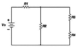
Solution: First of all we have labeled all elements and identified all relevant nodes in the circuit.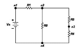
There are a few general guidelines that we need to remember as we make the selection of the reference node.
- A useful reference node is one which has the largest number of elements connected to it.
- A useful reference node is one which is connected to the maximum number of voltage sources.
For the next step we assign current flow and polarities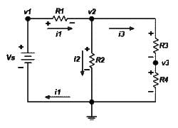
For node n1 voltage of the voltage source is known so v1 = Vs ……………………………(1)
& KCL at node n2 associated with voltage v2 gives: i1 = i2 + i3 ….………………………… (2)
The currents i1, i2, i3 are expressed in terms of the voltages v1, v2, v3 as follows

 ……….. (3)
From the relation (1) (2) & (3) we get…. 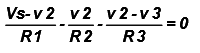 …………… (4)
Rewrite the above expression as a linear function of the unknown voltages v2 and v3 gives.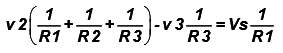 ………. (5)
KCL at node n3 associated with voltage v3 gives: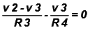
or 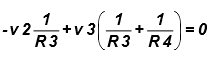 ....……. (6)
Now we can write equation (5) & (6) in matrix form for the node voltage v2 & v3.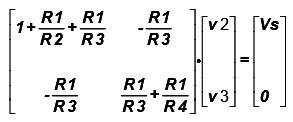
Or  ……… (7)
In defining the set of simultaneous equations, we want to end up with a simple and consistent form. The simple rules to follow and check are
- Place all sources (current and voltage) on the right hand side of the equation, as inhomogeneous drive terms.
- The terms comprising each element on the diagonal of the matrix must have the same sign.
- If you arrange so that all diagonal elements are positive, then the off-diagonal elements are negative and the matrix is symmetric: Aij = Aji. If the matrix does not have this property there is a mistake somewhere.
 must have the same sign.
Once we put the equations in matrix form and perform the checks detailed above the solutions then there is a solution if the  the unknown voltage VK is given by:
 ………… (8)
Where is the matrix
 with the k-th column replaced by the vector V.
So for our example the voltages v2 and v3 are given by: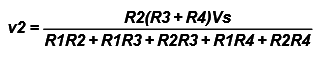 ……… (9)
 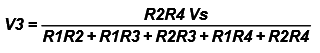 ……. (10)
Nodal Analysis with Floating Voltage Sources. (THE SUPERNODE)
If a voltage source V2 is not connected to the reference node it is called a floating voltage source and special care must be taken when performing the analysis of the circuit. In the circuit of given figure below the voltage source V2 is not connected to the reference node and thus it is a floating voltage source. Here v2 is the node voltage while V2 is the source voltage between node n2 & n3.
Circuit with a Supernode
The part of the circuit enclosed by the dotted ellipse is called a supernode. Kirchhoff’s current law may be applied to a supernode in the same way that it is applied to any other regular node. This is not surprising considering that KCL describes charge conservation which holds in the case of the supernode as it does in the case of a regular node.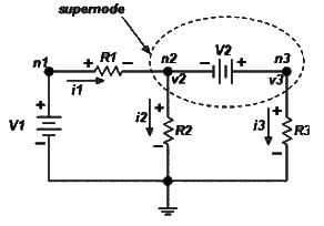
In our example application of KCL at the supernode gives I1 = i2 + I3 ………. (11)
In term of the node voltages Equation (11) becomes: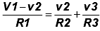 ………… (12)
The relationship between node voltages v1 and v2 is the constraint that is needed in order to completely define the problem. The constraint is provided by the voltage source V2.
V2 = v3 - v2 ………(13)
From equation (12) & (13)…..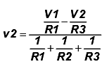
and 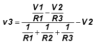 ..……..(14)
Example- Nodal Analysis with supernode.
Determine the node voltages v1, v2, and v3 of the circuit in Figure below?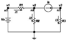
Solution: We have applied the first five steps of the nodal method and now we are ready to apply KCL to the designated nodes. In this example, the current source Is constraints the current i3 such that i3.
KCL at node n2 gives…
I1 = I2+Is …………….. (1)
And with the application of Ohm’s law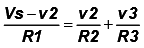 ………… (2)
Where we have used v1 = Vs at node n1.
The current source provides a constraint for the voltage v3 at node n3.
V3 = ISR3 ………. (3)
Now combining the equation (2)& (3).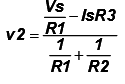 …….. (4)
MESH ANALYSIS
A mesh is defined as a loop which does not contain any other loops The procedure for obtaining the solution is similar to that followed in the Node method and the various steps are given below.
- Clearly, label all circuit parameters and distinguish the unknown parameters from the known.
- Identify all meshes of the circuit & assign mesh currents and label polarities.
- Apply KVL to each mesh and express the voltages in terms of the mesh currents.
- Solve the resulting simultaneous equations for the mesh currents.
- Now that the mesh currents are known, the voltages may be obtained from Ohm’s law.
EXAMPLE- Find out the mesh current i1 & i2 for mesh 1 & mesh 2?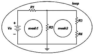
Solution: Our circuit example has three loops but only two meshes as show,the meshes of interest are mesh1 and mesh2.
In the next step we will assign mesh currents, define current direction and voltage polarities. The direction of the mesh currents I1 and I2 is defined in the clockwise direction as shown in the next figure.
The branch of the circuit containing resistor R2 is shared by the two meshes and thus the branch current (the current flowing through R2) is the difference of the two mesh currents.
Considering mesh1. For clarity we have separated mesh1 from the circuit in doing this, care must be taken to carry all the information of the shared branches. Here we indicate the direction of mesh current I2 on the shared branch.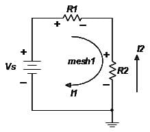
Apply KVL to mesh1. Starting at the upper left corner and proceeding in a clock-wise direction the sum of voltages across all elements encountered is
I1R1+ (I1-I2) R2-VS = 0 …………. (1)
Similarly, consideration of mesh2 : we have indicated the direction of the mesh current I1 on the shared circuit branch.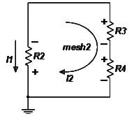
Apply KVL to mesh2:
I2 (R3 + R4) + (I2-I1) R2 = 0 ………………. (2)
From equation (1) & (2)…..
I1(R1+ R2) - I2 R2 = VS …………. (3)
-I1R2 + I2 (R2+R3+R4) = 0 ………… (4)
In matrix form equations (3) & (4) becomes…..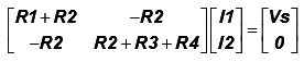 ………….. (5)
Equation (5) may now be solved for the mesh currents I1 and I2.
Note: It is evident from Figure next figure below that the branch currents are i1 , i2 & i3 are obtained from the mesh currents I1 & I2 such as.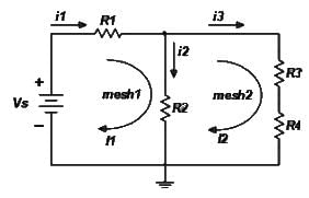
I1 = i1 i2 = I1 – I2 i3 = I2
MESH ANALYSIS WITH CURRENT SOURCES
1. If a current source exists only in one mesh.
(i) The mesh current is defined by the current source.
(ii) Number of variables is reduced.
2. If a current source exists between two meshes.
(i) The two nodes form a Supermesh.
(ii) Use one current variable for both meshes. The current difference between these two meshes is known.
(iii) Apply KVL to the Supermesh.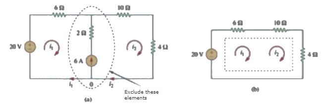
Example: Find out the unknown mesh current I1?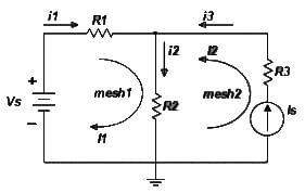
Solution: Consider the circuit in the figure which contains a current source. The application of the mesh analysis for this circuit does not present any difficulty once we realize that the mesh current of the mesh containing the current source is equal to the current of the current source:
i.e. I2 = IS ……………………………… (1)
In defining the direction of the mesh current, we have used the direction of the current IS. We also note that the branch current I3 = IS.
Applying KVL around mesh1 we obtain
I1R1 + (I1 + IS) R2 = VS ……………………………(2)
The above equation simply indicates that the presence of the current source in one of the meshes reduces the number of equations in the problem.
The unknown mesh current is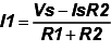
PRACTICE PROBLEMS WITH ANSWERS.
Q.1. Determine the currents in the given circuits with reference to the indicated direction?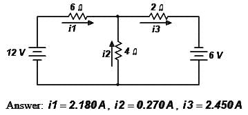
Q.2. Determine the currents in the given circuits with reference to the indicated direction?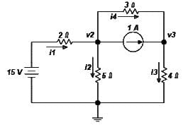
Answer: i1 = 3.31A, i2 = 1.68A, i3 =1.63A, i4 = 0.627A, v2 = 8.39V, v3 = 6.51V
|
68 videos|85 docs|62 tests
|
FAQs on Network Equation & Solution Methods - Network Theory (Electric Circuits) - Electrical Engineering (EE)
| 1. What is a network equation? |  |
| 2. What are the solution methods for network equations? | |
| 3. How are network equations used in electrical engineering? | |
| 4. Are there any software tools available for solving network equations? | |
| 5. How can network equations be applied in real-life applications? | |

|
4.97/5 Rating |

|
Dec 22, 2024 Last updated |

|
Explore Courses for Electrical Engineering (EE) exam
|
|
Viva Questions
,ppt
,Summary
,video lectures
,past year papers
,Previous Year Questions with Solutions
,Network Equation & Solution Methods | Network Theory (Electric Circuits) - Electrical Engineering (EE)
,shortcuts and tricks
,practice quizzes
,Exam
,Semester Notes
,Free
,Objective type Questions
,Extra Questions
,mock tests for examination
,MCQs
,study material
,Network Equation & Solution Methods | Network Theory (Electric Circuits) - Electrical Engineering (EE)
,Network Equation & Solution Methods | Network Theory (Electric Circuits) - Electrical Engineering (EE)
,Sample Paper
,Important questions
;


Network Equation & Solution Methods Free PDF Download
Importance of Network Equation & Solution Methods
Network Equation & Solution Methods Notes
Network Equation & Solution Methods Electrical Engineering (EE) Questions
Study Network Equation & Solution Methods on the App
|
© EduRev
|
Education Revolution
|


|


