Network Theorems - 2 | Network Theory (Electric Circuits) - Electrical Engineering (EE) PDF Download
| Table of contents |
|
| MILLMAN’S THEOREM |
|
| RECIPROCITY THEOREM |
|
| TELLEGEN'S THEOREM |
|
| SUBSTITUTION THEOREM |
|
| STAR-DELTA TRANSFORMATION |
|

MILLMAN’S THEOREM
Through the application of Millman’s theorem, any number of parallel voltage sources can be reduced to one. In the given figure below, for example, the three voltage sources can be reduced to one. This permits finding the current through or voltage across RL without having to apply a method such as mesh analysis, nodal analysis, superposition, and so on.
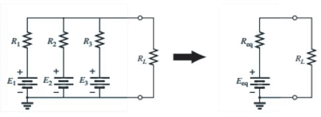
Basically, three steps are included in its application
Step 1: Convert all voltage sources to current sources.
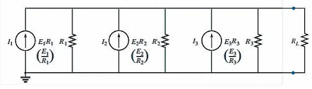
Step 2: Convert the parallel current source into resulting network below as
IT = I1+I2+I3 & RT = R1+R2+R3
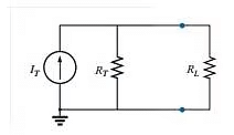
Step 3: Convert the resulting current source to a voltage source, and the desired single-source network is obtained as
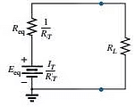
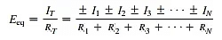
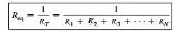
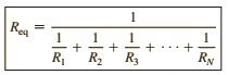
The plus-and-minus signs appear in last equation to include those cases where the sources may not be supplying energy in the same direction. The equivalent resistance is
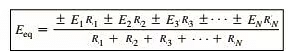
In terms of the resistance values,
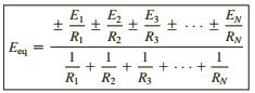
and
RECIPROCITY THEOREM
The reciprocity theorem is applicable only to single-source networks. The theorem states that the current I in any branch of a network due to a single voltage source E anywhere else in the network will equal the current through the branch in which the source was originally located if the source is placed in the branch in which the current I was originally measured.
In other words, the location of the voltage source and the resulting current may be interchanged without a change in current. The theorem requires that the polarity of the voltage source have the same correspondence with the direction of the branch current in each position.
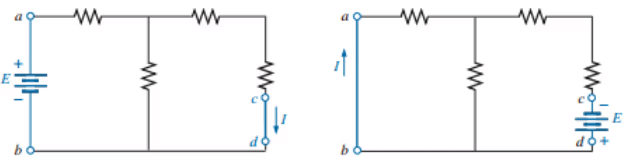
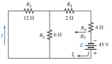
Example: verify reciprocity theorem.
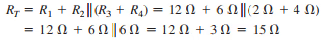
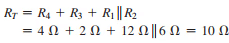
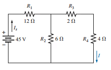 The Total resistance is
 and
and 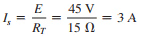
with 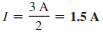
Interchanging the location of E and I of last figure to demonstrate the validity of the reciprocity theorem.
and 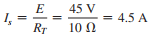
so that 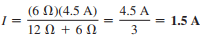
with agrees with the above.
TELLEGEN'S THEOREM
- Tellegen’s theorem is based on two Kirchhoff’s laws and is applicable for any lumped network having elements which are linear or non-linear, active or passive, time-varying or time-invariant.
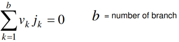
- For a lumped network whose element assigned by associate reference direction for branch voltage vk and branch current jk.The product vkjk is the power delivered at time t by the network to the element k.
- If all branch voltages and branch currents satisfy KVL and KCL then
Application of Tellegen's Theorem:
As seen from last equation Tellegen’s Theorem implies the law of energy conservation.“The sum of power delivered by the independent sources to the network is equal to the sum of the power absorbed by all branches of the network”. so the application of Tellegen's theorem can be classified as- Conservation of energy
- Conservation of complex power
- The real part and phase of driving point impedance
- Driving point impedance
SUBSTITUTION THEOREM
The substitution theorem states that If the voltage across and the current through any branch of a dc bilateral network are known, this branch can be replaced by any combination of elements that will maintain the same voltage across and current through the chosen branch.
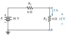
More simply, the theorem states that for branch equivalence, the terminal voltage and current must be the same. Consider the circuit in in which the voltage across and current through the branch a-b are determined. Through the use of the substitution theorem, a number of equivalent a-a′ branches are shown Note that for each equivalent, the terminal voltage and current are the same.
- Through the use of the substitution theorem, a number of equivalent branches are
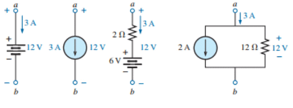
Note that for each equivalent, the terminal voltage and current are the same.a known potential difference and current in a network can be replaced by an ideal voltage source and current source, respectively
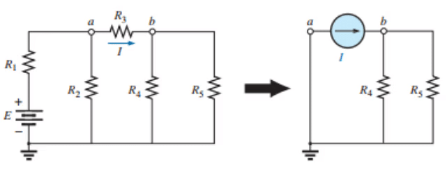
Example:
The current source equivalence where a known current is replaced by an ideal current source, permitting the isolation of R4 and R5.
Recall from the discussion of bridge networks that V = 0 and I = 0 were replaced by a short-circuit and an open circuit, respectively. This substitution is a very specific application of the substitution theorem.
STAR-DELTA TRANSFORMATION
- A part of a larger circuit that is configured with three-terminal network Y (orΔ) to convert into an equivalent Δ (or Y) through transformations.
- Application of these transformations will be studied by solving resistive circuits.
Delta (Δ) – Wye (Y) conversion:
Let us consider the network shown below and assumed the resistances (RAB, RBC, RCA) in Δ network are known. Our problem is to find the values of in Wye (Y) network that will produce the same resistance when measured between similar pairs of terminals. We can write the equivalence resistance between any two terminals in the following form.
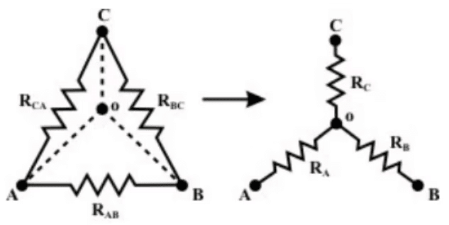
Between A & C terminals:
Between C & B terminals:
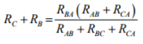
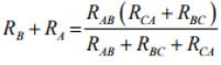
Between B & A terminals:
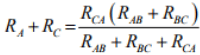
By combining above three equations, one can write an expression as given below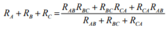
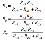
- on solving above equations we get for star network resistances
Conversion from Star or Wye (Y) to Delta (Δ):
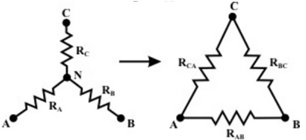
- To convert a Wye (Y) to a Delta (Δ), the relationships RAB, RBC & R3 must be obtained in terms of the Wye (Y) resistances RA RB and RC Considering the Y connected network, we can write the current expression through RA resistor as
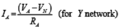 Appling KCL at ‘ N ’ for Y connected network (assume A, B, C terminals having higher potential than the terminal N) we have,

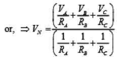
Few Δ-networkCurrent entering at terminal A = Current leaving the terminal ‘ A ’
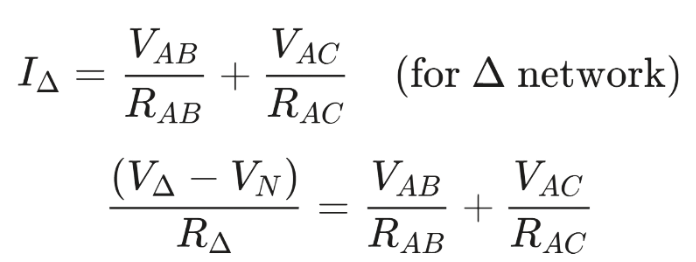 Using the VN expression in the above equation, we get
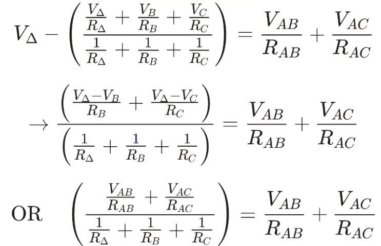
- Equating the coefficients of VABand VAC in both sides we obtained the following relationship.
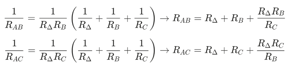
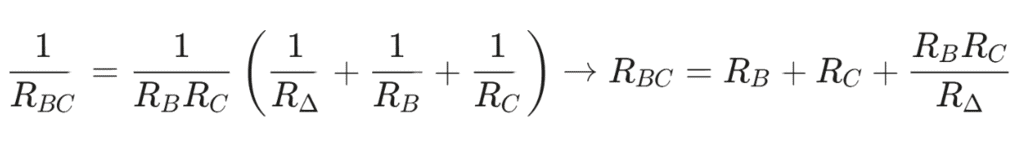
- similarly we can obtain for RBC for equivalent delta configuration
 Observations: In order to note the symmetry of the transformation equations, the Wye (Y ) and Delta (Δ) networks have been superimposed on each other.
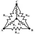
- The equivalent star (Wye) resistance connected to a given terminal is equal to the product of the two Delta (Δ) resistances connected to the same terminal divided by the sum of the Delta (Δ) resistances.
- The equivalent Delta (Δ) resistance between two-terminals is the sum of the two star (Wye) resistances connected to those terminals plus the product of the same two star (Wye) resistances divided by the third-star resistance.
|
73 videos|139 docs|62 tests
|
FAQs on Network Theorems - 2 - Network Theory (Electric Circuits) - Electrical Engineering (EE)
| 1. What is Millman's Theorem and how is it used in electrical engineering? |  |
| 2. Can you explain the Reciprocity Theorem and its significance in circuit analysis? | |
| 3. What is Tellegen's Theorem and how does it apply to network analysis? | |
| 4. How does the Substitution Theorem work in electrical circuits? | |
| 5. What is the Star-Delta Transformation and when is it used? | |


Semester Notes
,study material
,Viva Questions
,Summary
,Network Theorems - 2 | Network Theory (Electric Circuits) - Electrical Engineering (EE)
,ppt
,Previous Year Questions with Solutions
,Exam
,Network Theorems - 2 | Network Theory (Electric Circuits) - Electrical Engineering (EE)
,practice quizzes
,Objective type Questions
,Important questions
,Network Theorems - 2 | Network Theory (Electric Circuits) - Electrical Engineering (EE)
,Sample Paper
,MCQs
,past year papers
,shortcuts and tricks
,Free
,mock tests for examination
,video lectures
,Extra Questions
,


Network Theorems - 2 Free PDF Download
Importance of Network Theorems - 2
Network Theorems - 2 Notes
Network Theorems - 2 Electrical Engineering (EE) Questions
Study Network Theorems - 2 on the App
|
© EduRev
|
Education Revolution
|


|


