Study Notes - Two Port Network | Network Theory (Electric Circuits) - Electrical Engineering (EE) PDF Download
TWO PORT NETWORK
- A pair of terminals through which a current may enter or leave a network is known as a port.
- Two-terminal devices or elements (such as resistors, capacitors, and inductors) result in one-port networks.
- The four-terminal or two-port circuits are used in op amps, transistors, and transformers.
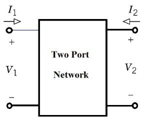
- Two Port Network circuit is shown below.

- The current entering one terminal leaves through the other terminal so that the net current entering the port equals zero.
- A two-port network consists of two pairs of terminals in which one pair of terminals is designated as input and other pair being output.
- Two port networks are useful in communications, control systems, power systems, and electronics.
- To characterize a two-port network requires that we relate the terminal quantities V1, V2, I1, and I2. The various terms that relate these voltages and currents are called parameters.
- When the voltage or current are compared at same port then the term defined the Driving Imminence Function,while on the other hand when the comparison is done at different port then the function will defined as Transfer Imminence Function.
1. (Z-parameters) Open circuit Impedance Parameters
Its use is premised on selecting the input port current, I1, and the output port current, I2, as independent electrical variables.
where the zij are called the z-parameters of a two-port network. Here, input and output voltages are expressed in terms of input and output currents. The equations are given below.
V1 = Z11I1 + Z12I2
V2 = Z21I1 + Z22I2
where, Z11, Z12, Z21 and Z22 are called the Z-parameters.
So the Z-Parameter can be found as follow: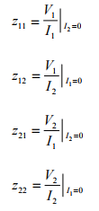
The z-parameters are also called open-circuit impedance parameters since they are obtained as a ratio of voltage and current and the parameters are obtained by open-circuiting port 2 (I2 = 0) or port 1 (I1 = 0).
- Z11 is the driving Point impedance when output is open circuited.
- Z12 is the reverse transfer impedance when input is open-circuited.
- Z21 is the forward transfer impedance when output is open-circuit.
- Z22 is the driving Point impedance when input is open-circuited.
2. (Y-parameters) Short Circuit Admittance parameters
These parameters are obtained by expressing currents at two ports in terms of voltages at two ports.Thus, voltages V1 and V2 are independent variables, while I1 and I2 are dependent variables.
The equations are given below.
I1 = Y11V1 + Y12V2
I2 = Y21V1 + Y22V2
Where, Y11, Y12, Y21, Y22 are called the Y-parameters.
The y-parameters are also called short-circuit admittance parameters. They are obtained as a ratio of current and voltage and the parameters are found by short-circuiting port 2 (V2 = 0) or port 1 (V1 = 0).
So the Y-Parameter can be found as follow:
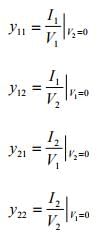
- Y11 Short-circuit driving point input admittance
- Y12 Short-circuit reverse transfer admittance
- Y21 Short-circuit forward transfer admittance
- Y22 Short-circuit driving point output admittance
3. h-parameters: Hybrid Parameters
- These parameters are obtained by expressing voltage at input port and the current at the output port.
- Two-port network variables selected as independent are the input current and the output voltage.
- The input voltage and the output current are the dependent variables of this model.
Equations for voltage at input port and current at the output port are given below.
V1 = h11I1 + h12V2
I2 = h21I1 + h22V2
The h-Parameter can be found as follow: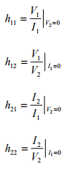
- h11 Short-circuit input impedance:
- h21 Forward short-circuit current gain it is dimensionless.
- h12 Reverse open-circuit voltage gain it is dimensionless :
- h22 Open-circuit output admittance:
The h-parameters are also called hybrid parameters since they contain both open-circuit parameters (I1 = 0) and short-circuit parameters (V2 = 0).
4. (g-parameters) Inverse hybrid parameters
- These parameters are obtained by expressing voltage at output port and the current at the input port.
- Off-diagonal g-parameters are dimensionless, while diagonal members have dimensions the reciprocal of one another.
I1 = g11V1 + g12I2
V2 = g21V1 + g22I2

Here g12 and g21 are dimensionless coefficients, g22 is impedance and g11 is admittance.
5. (T-Parameters) or ABCD parameters Transmission Parameters
These are generally used in the analysis of power transmission in which the input port is referred as the sending end while the output port is referred as receiving end. These parameters can be obtained by expressing voltage and current at the output port.
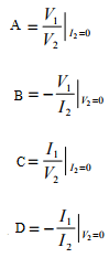
ABCD parameters can be defined as following:
- A is the reverse voltage ratio with open output.
- B is the reverse transfer impedance with shorted output.
- C is the reverse transfer admittance with open output.
- D is the reverse current ratio with shorted output.
V1 = AV2 + B(–I2)
I1 = CV2 + D(–I2)
The transmission parameters express the primary (sending end) variables V1 and I1 in terms of the secondary (receiving end) variables V2 and ' -I2 '. The negative of I2 is used to allow the current to enter the load at the receiving end.
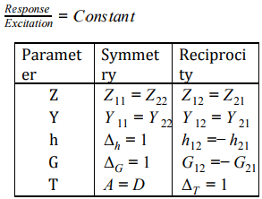
- Symmetry Condition: if input impedance seen through both the port is same then both port are known as symmetric port.If port are symmetric then both port can be interchanged.
- Reciprocity Condition: If only single source is acting in the circuit then “By changing the position of response and excitation if ratio of response is to excitation is constant then circuit is reciprocal”.
6. Conversion of Z-parameter in term of Y-parameter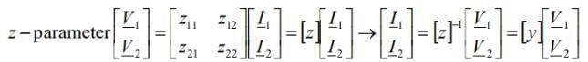
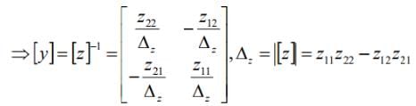
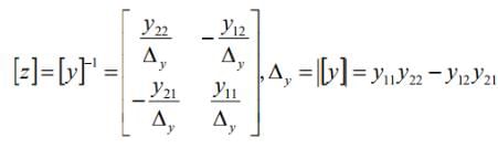
- In the similar fashion we can obtain the other relationship
7. INTERCONNECTION OF TWO-PORT NETWORKS
Two-port networks can be connected in series, parallel or cascade. the configuration listed below:
- Series Connection: When two 2-port network are connected in series configuration the z- parameter of each port will be directly added in the result of equivalent 2-port network.
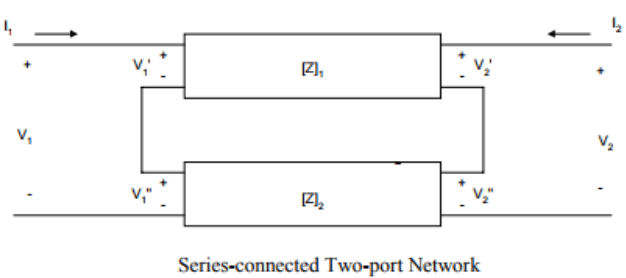
This can be concluded that if two-port networks with Z-parameters [Z]1,[Z]2,[Z]3,[Z]n , are connected in series, then the equivalent two port-parameters are given as
[Z]eq = [Z]1+ [Z]2+ [Z]3+ [Z]n
- Parallel-connected Two-port Network: When two 2-port network are connected in Parallel configuration the Y- parameter of each port will be directly added in the result of equivalent 2-port network.
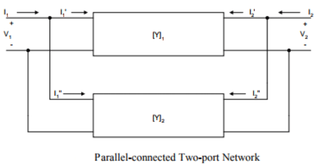
This can be concluded that if two-port networks with Y-parameters [Y]1,[Y]2,[Y]3,[Y]n, are connected in Parallel, then the equivalent two port-parameters are given as
[Y]eq = [Y]1+ [Y]2+ [Y]3+ [Y]n
- Cascade Connection of Two-port Network:
When two 2-port network are connected in cascaded configuration then the T-parameter of equivalent two port network will be the Product of T-parameter of individual network.
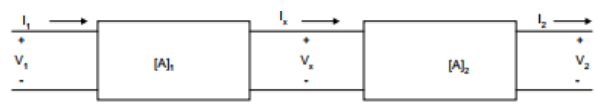
networks have transmission parameters [A]1,[A]2,[A]3,[A]n, then the equivalent two-port parameter will have a transmission parameter given as
[A]eq = [A]1*[A]2*[A]3*[A]n
|
68 videos|85 docs|62 tests
|
FAQs on Study Notes - Two Port Network - Network Theory (Electric Circuits) - Electrical Engineering (EE)
| 1. What is a two-port network in electrical engineering? |  |
| 2. How do you determine the parameters of a two-port network? | |
| 3. What is the significance of two-port network analysis in electrical engineering? | |
| 4. How can two-port networks be used to design amplifiers? | |
| 5. Can two-port network analysis be used for transmission line analysis? | |

|
4.82/5 Rating |

|
Dec 22, 2024 Last updated |

|
Explore Courses for Electrical Engineering (EE) exam
|
|
Summary
,MCQs
,Extra Questions
,Semester Notes
,Study Notes - Two Port Network | Network Theory (Electric Circuits) - Electrical Engineering (EE)
,Viva Questions
,study material
,shortcuts and tricks
,ppt
,Study Notes - Two Port Network | Network Theory (Electric Circuits) - Electrical Engineering (EE)
,mock tests for examination
,past year papers
,Sample Paper
,Previous Year Questions with Solutions
,Free
,Study Notes - Two Port Network | Network Theory (Electric Circuits) - Electrical Engineering (EE)
,practice quizzes
,video lectures
,Exam
,Important questions
,Objective type Questions
;


Study Notes - Two Port Network Free PDF Download
Importance of Study Notes - Two Port Network
Study Notes - Two Port Network
Study Notes - Two Port Network Electrical Engineering (EE) Questions
Study Study Notes - Two Port Network on the App
|
© EduRev
|
Education Revolution
|


|


