Study Notes For Single Phase AC Circuit | Network Theory (Electric Circuits) - Electrical Engineering (EE) PDF Download
AC CIRCUIT ANALYSIS
ALTERNATING QUANTITY: An alternating quantity is that which acts in alternate directions and whose magnitude undergoes a definite cycle of changes in definite intervals of time.
ALTERNATING VOLTAGE: Alternating voltage may be generated by
- By rotating a coil in a stationary magnetic field.
- By rotating a magnetic field within a stationary coil.
ADVANTAGES OF SINE WAVE
- Any periodic non-sinusoidal wave can be expressed as the sum of a number of Sine wave of different frequencies.
- A sine wave can be expressed in a simple mathematical form.
- The resultant of two or more quantities varying sinusoidally at the same frequency is another sinusoidal quantity of same frequency.
- The rate of change of any sinusoidal quantity is also sinusoidal.
CYCLE: A cycle may be defined as one complete set of positive and negative values of an alternating quantity repeating at equal intervals. Each complete cycle is spread over 360° electrical.

PERIODIC TIME: The time taken by an alternating quantity in seconds to trace one complete cycle is called periodic time or time-period. It is usually denoted by symbol T.
FREQUENCY: The number of cycles per second is called frequency and is denoted by symbol f.
f = 1/T
If the angular velocity w is expressed in radians per second, then
w= 2π/T
w = 2πf
Peak Factor: Ratio of maximum value to the RMS value is known as crest or peak.
factor or amplitude factor.
Peak factor = Maximum Value/RSM Value
Form Factor: Ratio of RMS Value to average value is known as form factor.
Form Factor = RMS Value/Average Value
PHASE DIFFERENCE

ACTIVE, REACTIVE & APPARENT POWER OF AC CIRCUIT
- When the current is out of phase with the voltage the power indicated by the product of the applied voltage and the total current gives only what is known as apparent power and measured in volt-amperes.
- The power that is returned to the source by the reactive components in the circuit is called reactive power and is measured in VAR.
- The power that actually used in the circuit (dissipated in resistance) is true or active power and is measured in watts or kW.
Impedence in AC circuit Z = R ± jX = |Z|∠Φ= |Z| cosv + j|Z| sinΦ
where X = j|(XL-XC)|
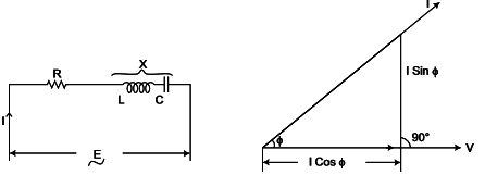
where |Z| = √R2 + X2
R= |Z| cosΦ
X= |Z| sinΦ
Power Factor of the circuit ⇒ cosΦ = R/Z
Current in the circuit = E/Z
This current has two components I cosΦ and I sinΦ. The component I cosΦ is called in phase or watt full component and I sinΦ is perpendicular to E and is called wattless component.
Active (Real) Power = Voltage x Current x cosΦ watts
The total power EI in volt-amperes supplied to a circuit consists of two components
(a) Active power = EI cosΦ watts
(b) Reactive power = EI sinΦ volt-amperes reactive or simply VAR.

OA = Active power = EI cosΦ presented by watts
AB = Reactive power = EI sin Φ expressed by VAR
OB = Total power = EI expressed by VA
4. RESONANCE IN AC CIRCUIT
SERIES RESONANCE
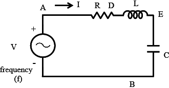
The circuit, with resistance R, inductance L, and a capacitor, C in series is connected to a single-phase variable frequency (f) supply.
The total impedance of the circuit is
Z∠Φ = R+j(XL-XC)
where XL = jwL
XC = 1/jwC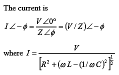
The current in the circuit is maximum, if 
The frequency under the above condition is
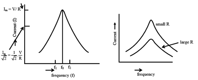
The magnitude of the impedance under the above condition is |Z = R, with the reactance X = 0, as the inductive reactance is equal to capacitive reactance. The phase angle is φ = 0, and the power factor is unity (cos φ= 1), which means that the current is in phase with the input (supply) voltage. So, the magnitude of the current I = V/R.
The magnitude of the voltage drop in the inductance L/capacitance C, both are equal as the reactance are equal is⋅= (I.woL = I.1/(woC)
Quality Factor Q = woL/R = 2πfoL/R = 1/R √L/C
The impedance of the circuit with the constant values of inductance L, and capacitance C is minimum at resonant frequency (fo), and increases as the frequency is changed, i.e. increased or decreased, from the above frequency. The current is maximum at f=fo , and decreases as frequency is changed (f>fo or f<fo) i.e. f≠fo.
PARALLEL RESONANCE
The circuit, with resistance R, inductance L, and a capacitor, C in parallel is connected to a single-phase variable supply frequency (f).
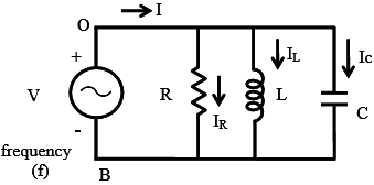
The total admittance of the circuit is
Y∠Φ = 1/R + J(wC-1/wL)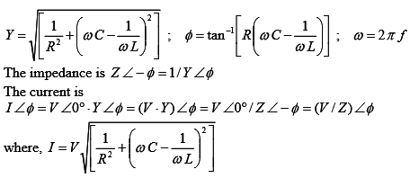
The current in the circuit is maximum, if 
The frequency under the above condition is
The magnitude of the impedance under the above condition is (|Z|=R), while the magnitude of the admittance is (|Y| = (1/R)= G). The reactive part of the admittance is B =0, as the susceptance (inductive) BL = (1/ωL) is equal to the susceptance (capacitive) BC = ωC. The phase angle is φ = 0, and the power factor is unity (cos φ=1).
The input current increases as the frequency are changed, i.e. increased or decreased from the resonant frequency (f>fo or f<fo) i.e.f≠fo.
POWER IN AC CIRCUIT
We saw in our tutorial about Electric Power that AC circuits which contain resistance and capacitance or resistance and inductance, or both, also contain real power and reactive power. So in order for us to calculate the total power consumed, we need to know the phase difference between the sinusoidal waveform of the voltage and current.
The phase angle is given by,
φ = arg(V) − arg(I)
i.e. the angle from the current to the voltage. Therefore, positive phase angles mean that the current lags the voltage, and thus are called lagging, and negative phase angles mean that the current leads the voltage, and are called leading.
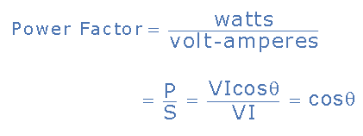
The power factor is defined as,
power factor = P/S = cos(φ)
As this is always a positive number the tag ‘leading’ or ‘lagging’ is usually added to describe the phase difference.
where P (=VI cosφ )is the Real Power
S(= VI) is the Apparent Power.
Real Power in AC Circuit
- Real power P, so called true or active power, performs the “real work” within an electrical circuit. Real power, measured in watts, defines the power consumed by the resistive part of a circuit.
- Then real power, P in an AC circuit is the same as power, P in a DC circuit. So just like DC circuits, it is always calculated as I2R, where R is the total resistive component of the circuit.
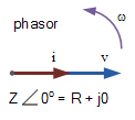
- Since resistance does not produce any phase difference between voltage and current waveform, all the useful power is delivered directly to the resistance and converted to heat, light, and work.
- Hence the power consumed by a resistance is the real power which is fundamentally the circuits average power.
Real Power P = I2R = V*I*cos(θ) Watts, (W)
- since there is no phase difference the phase shift between the two waveforms will be zero (0). Then:
P = Vrms x Irms x Cosθ ⇒ since cos 00=1
So P = Vrms x Irms x 1
or {P = Vrms x Irms}
- Real power I2R resistive measured in watts, which is we read on our utility energy meter and has units in Watts (W), Kilowatts (kW), and Megawatts (MW).
- Note that real power, P is always positive.
Reactive Power in AC Circuit:
- Reactive power Q,(also called wattless power) the power consumed in an AC circuit which does not perform any useful work but has a big effect on the phase shift between the voltage and current waveforms.
- Reactive power is linked to the reactance produced by inductors and capacitors and counteracts the effects of real power. Reactive power does not exist in DC circuits.
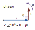
- Unlike real power (P), reactive power (Q) takes power away from a circuit due to the creation and reduction of both inductive magnetic fields and capacitive electrostatic fields, thereby making it harder for the true power to supply power directly to a circuit or load.
- The power stored by an inductor in its magnetic field tries to control the current, while the power stored by a capacitors electrostatic field tries to control the voltage.
- The result is that capacitors “generate” reactive power and inductors “consume” reactive power. This means that they both consume and return power to the source so none of the real power is consumed.
Reactive Power Q = I2X = V*I*sin(θ) volt-amperes reactive, (VAr’s)
Q = Vrms x Irms x Sinθ ⇒ since from phasor, sin 900=1
Q = Vrms x Irms x 1
Q = Vrms x Irms
Thus reactive power is the I2X reactive element that has units in volt-amperes reactive (VAr), Kilovolt-amperes reactive (kVAr), and Megavolt-amperes reactive (MVAr).
Apparent Power in AC Circuit
- There is a relationship between the real power (P), and the reactive power (Q), called the complex power.
- The product Vrms & Irms circuit is called the “volt-ampere product” (VA) given the symbol S and whose magnitude is known generally as apparent power.
- This complex Power is not equal to the algebraic sum of the real and reactive powers added together but is instead the vector sum of P and Q given in volt-amps (VA).
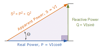
Where:
- P is the I2R or Real power that performs work measured in watts, W.
- Q is the I2X or Reactive power measured in volt-amperes reactive, VAr.
- S is the I2Z or Apparent power measured in volt-amperes, VA.
- θ is the phase angle in degrees. The larger the phase angle, the greater the reactive power.
- Cosθ = P/S = W/VA = power factor, p.f.
- Sinθ = Q/S = VAr/VA.
- Tanθ = Q/P = VAr/W.
The power factor is calculated as the ratio of the real power to the apparent power because this ratio equals cosθ.
Power Factor in AC Circuit
- Power factor, cosθ, is an important part of an AC circuit, can express in terms of circuit impedance or circuit power.
- Power factor is defined as the ratio of real power (P) to apparent power (S).
- In a pure resistive circuit, the current and voltage are in-phase with each other so the real power consumed is the same as the apparent power as the phase difference is zero degrees (0o).
So the power factor will be:
Power Factor, pf = cos 0o = 1.0
Which means that the number of watts consumed is the same as the number of volt-amperes consumed producing a power factor of 1.0, or 100%. In this case, it is referred to a unity power factor.
In a purely reactive circuit, the current and voltage out-of-phase with each other by 90o.
the power factor, in this case, will be:
Power Factor, pf = cos 90o = 0
Which means that the number of watts consumed is zero but there is still a voltage and current supplying the reactive load.
- Hence we concluded that reducing the reactive VAr component of the power triangle will cause θ to reduce improving the power factor towards one, unity.
- It is also desirable to have a high power factor as this makes the most efficient use of the circuit delivering current to a load.
Real Power (P) = Apparent power (S) x Power factor (p.f)
The disadvantage of Low Power Factor:
Poor power Factor or Low Power Factor less than unity has the following disadvantage:
- Effect on Transmission lines(Greater conductor size): At low power factor, to transmit or distribute the power at a constant voltage requires more current. To transmit high current, higher conductor size transmission lines are needed. This increases the cost of transmission lines.
- Effect on Generators, Transformers: It is known that the electrical machinery (Generators, Transformers) etc are rated in KVA rather than kW.
Where KVA = KW/power factor
i.e The KVA is inversely proportional to KVA for a given KW. For lower power factor the electrical machinery should be having higher KVA rating to drive constant KW load. Then the size and cost of the electrical machine become expensive.
- High losses in power system: Due to the high current for low power factor, the copper losses increase in the transmission conductors and switch gear machinery.
- High Voltage drops (poor voltage regulation): The large current at low lagging power factor causes greater voltage drops in alternators, transformers, and transmission lines. This results in a decrease in voltage at the driving end and enables the use of extra equipment to counteract the voltage drop like voltage stabilizers. This increase the cost of the power supply system.
How to avoid low power factor? (or) What are the various methods to avoid low power factor?
- As far as possible, overexcited synchronous motors have to be used in place of induction motors.
- High-speed induction motors have better power factor than low-speed induction motors. They are smaller in frame size and economical too.
- The induction motors have maximum power factor when fully loaded. So we should try to use induction motors at full load condition.
Various methods of power factor improvement are given below;
- Using Static capacitors
- Using synchronous motors
- Using synchronous condensers
- Using Phase advancers
- Using synchronous induction motors
- Using high power factor motors
|
73 videos|139 docs|62 tests
|
FAQs on Study Notes For Single Phase AC Circuit - Network Theory (Electric Circuits) - Electrical Engineering (EE)
| 1. What is a single-phase AC circuit? |  |
| 2. How does a single-phase AC circuit work? |  |
| 3. What are the components of a single-phase AC circuit? |  |
| 4. What is the difference between single-phase and three-phase AC circuits? |  |
| 5. How can I calculate the power in a single-phase AC circuit? |  |


