Past Year Questions: Torsion of Shafts & Pressure Vessels | Solid Mechanics - Mechanical Engineering PDF Download

Q1: A 3 m long, horizontal, rigid, uniform beam PQ has negligible mass. The beam is subjected to a 3kN concentrated vertically downward force at 1 m from P, as shown in the figure. The beam is resting on vertical linear springs at the ends P and Q. For the spring at the end P, the spring constant Kp = 100kN/m. [2024, Set-ll]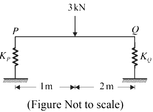
If the beam does not rotate under the application of the force and displaces only vertically, the value of the spring constant KQ (in kN/m) for the spring at the end Q is
(a) 200
(b) 50
(c) 100
(d) 150
Ans: (b)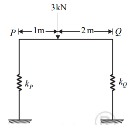
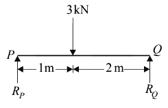
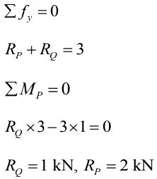
∴ ΔP = ΔQ
2/100 = 1/KQ
KQ = 50 kN/m
Hence, the correct option is (b).
Q2: A homogeneous shaft PQR with fixed supports at both ends is subjected to a torsional moment T at point Q, as shown in the figure. The polar moments of inertia of the portions PQ and QR of the shaft with circular cross-sections are J1 and J2 respectively. The torsional moment reactions at the supports P and R are TP and TR , respectively. [2024, Set-l]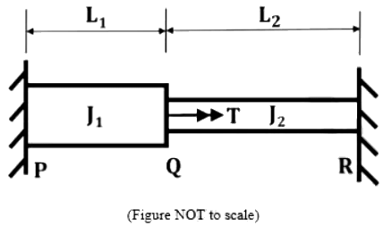 If Tp /TR = 4 and J1 /J2 = 2. The ratio of the lengths L1 /L2 is
(a) 2
(b) 4
(c) 0.25
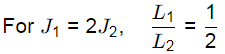
(d) 0.5
Ans: (d)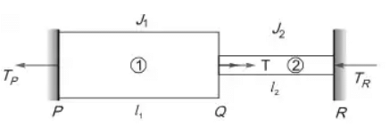 Let TP and TR be the resistive torques at support P and R respectively From equilibrium. Condition,
∵ TP + TR = T
TP = 4TR
⇒ TR = T/5 and TP = 4T/5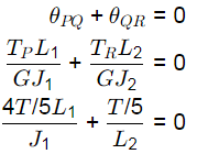
Q3: A circular solid shaft of span L= 5 m is fixed at one end and free at the other end. A torque T = 100 k N.m is applied at the free end. The shear modulus and polar moment of inertia of the section are denoted as G and J, respectively. The torsional rigidity GJ is 50, 000kN.m2/rad. The following are reported for this shaft: [2023, Set-ll]
Statement i) The rotation at the free end is 0.01 r a d rad
Statement ii) The torsional strain energy is 1.0 kN.m
With reference to the above statements, which of the following is true?
(a) Both the statements are correct
(b) Statement i) is correct, but Statement ii) is wrong
(c) Statement i) is wrong, but Statement ii) is correct
(d) Both the statements are wrong
Ans: (b)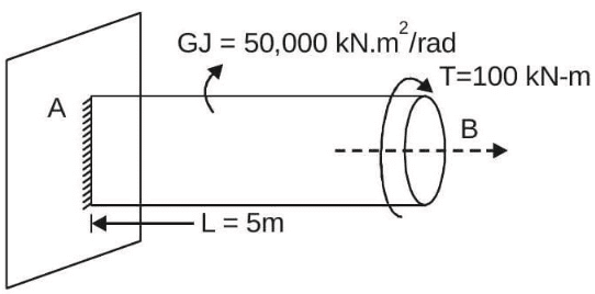
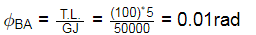
⇒ Torsional strain energy (U)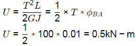
Hence, statement (i) correct and statement (ii) is incorrect.
Q4: A solid circular torsional member OPQ is subjected to torsional moments as shown in the figure (not to scale). The yield shear strength of the constituent material is 160 MPa. [2021, Set-ll] The absolute maximum shear stress in the member (in MPa, round off to one decimal place) is ________
(a) 15.3
(b) 12.6
(c) 18.2
(d) 11.8
Ans: (a)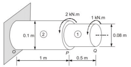
Absolute max shear stress =15.27 N/mm2
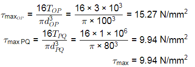
Q5: A plane frame shown in the figure has linear elastic springs at node H. The spring constants are kx = ky = 5 × 10⁵ kN/m and kθ = 3 × 10⁵ kNm/rad. [2019, Set-ll]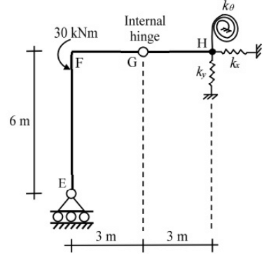 For the externally applied moment of 30 kNm at node F, the rotation (in degrees, round off to 3 decimals) observed in the rotational spring at node H is_____
(a) 0.001
(b) 0.003
(c) 0.005
(d) 0.009
Ans: (c)
No moment can be taken by segment FE.
∴ MFE = 0 Mθ = kθ × θ
30kNm = 3 × 10⁵ × θ
θ = 1 × 10⁻⁴ radians
= 0.0057∘
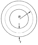
Q6: A closed thin-walled tube has thickness, t, mean enclosed area within the boundary of the centerline of tube's thickness, Am and shear stress, τ. Torsional moment of resistance T, of the section would be [2019 : 1 Mark, Set-ll]
(a) 2τAmt
(b) 4τAmt
(c) τAmt
(d) 0.5τAmt
Ans: (a)
Shear stress, 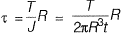
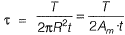
∴ 
Q7: A solid circular beam with radius of 0.25 m and length of 2 m is subjected to a twisting moment of 20 kNm about the z-axis at the free end, which is the only load acting as shown in the figure. The stress component τry at Point ‘ M ’ in the cross- section of the beam at a distance of 1 m from the fixed end is [2018 : 1 Mark, Set-I]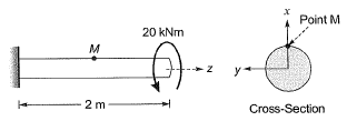 (a) 0.0 MPa
(b) 0.51 MPa
(c) 0.815 MPa
(d) 2.0 MPa
Ans: (a)
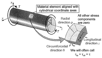
The only non-zero stresses are  if θ is 900 then θ = y
Hence 
= 16T/πd3 = 0.815 MPa
But in rest of the planes shear stresses are zero, hence, 
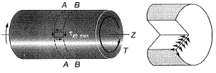
Q8: A hollow circular shaft has an outer diameter of 100 mm and inner diameter of 50 mm. If the allowable shear stress is 125 MPa, the maximum torque (in kN-m) that the shaft can resist is _____. [2017 : 2 Marks, Set-II]
Ans:

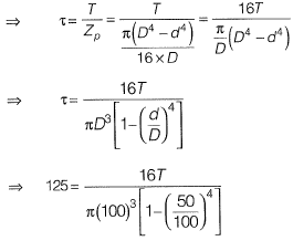
⇒ T = 23 kNm
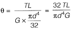
Q9: A solid circular shaft of diameter d and length L is fixed at one end and free at the other end. A torque T is applied at the free end. The shear modulus of the material is G. The angle of twist at the free end is [2010 : 1 Mark]


Ans: (b)
Angle of twist is given by,
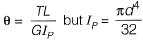
⇒ 
|
33 videos|72 docs|29 tests
|
FAQs on Past Year Questions: Torsion of Shafts & Pressure Vessels - Solid Mechanics - Mechanical Engineering
| 1. What is the basic formula for calculating the torsional stress in a circular shaft? |  |
| 2. How do you determine the angle of twist in a shaft subjected to torsion? | |
| 3. What are the common failure modes of pressure vessels? | |
| 4. What is the significance of the design pressure in pressure vessels? | |
| 5. How do you calculate the maximum allowable working pressure (MAWP) for a cylindrical pressure vessel? | |


Viva Questions
,study material
,Important questions
,Exam
,video lectures
,mock tests for examination
,ppt
,practice quizzes
,Previous Year Questions with Solutions
,Semester Notes
,Extra Questions
,Objective type Questions
,Past Year Questions: Torsion of Shafts & Pressure Vessels | Solid Mechanics - Mechanical Engineering
,Past Year Questions: Torsion of Shafts & Pressure Vessels | Solid Mechanics - Mechanical Engineering
,MCQs
,Summary
,shortcuts and tricks
,past year papers
,Past Year Questions: Torsion of Shafts & Pressure Vessels | Solid Mechanics - Mechanical Engineering
,Sample Paper
,Free
;


Past Year Questions: Torsion of Shafts & Pressure Vessels Free PDF Download
Importance of Past Year Questions: Torsion of Shafts & Pressure Vessels
Past Year Questions: Torsion of Shafts & Pressure Vessels Notes
Past Year Questions: Torsion of Shafts & Pressure Vessels Mechanical Engineering
Study Past Year Questions: Torsion of Shafts & Pressure Vessels on the App
|
© EduRev
|
Education Revolution
|


|


within 7 days!