Chapter 11 - Machines (Part-3) - Mechanical Engineering PDF Download

5. Principles of Electro Mechanical Energy Conversion
- Law of conservation of energy: energy can neither be created nor be destroyed, but it can be changed from one form to another form.
- The device used for energy conversion is called an energy conversion device (ECD). Examples:
(i) Motor's generators (high energy conversion devices.)
(ii) microphones and telephones receivers (low energy conversion devices)
(iii) relays, moving coil and moving iron instruments, and actuators, (in these devices the translator motion produces a small force or torque). - Electromechanical energy conversion devices (EMECD);: They change the form of energy from mechanical to electrical (for Ex: Generators) or from electrical to mechanical (for Eg: Motors)
- Motors and generators are continuous energy conversion devices
- An EMECD mainly consists of three essential parts as shown in fig (i). They are
1. Electrical system
2. Coupling field systems
3. mechanical system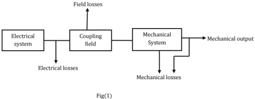
- In all the three systems, there are losses.
- The coupling field may be a magnetic field or an electric field.
- The energy storage capacity of a magnetic field is nearly 30,000 times that of an electric field. Most of the emecd's use magnetic field as the coupling field.
- The magnetic field is the coupling medium between the electrical and mechanical systems
- Assuming the motoring operation, the energy transfer equation is

Losses
- In electrical system: I2Rlosses.
- In the magnetic field: core loss due to changing magnetic flux in the core,
- In the mechanical system: Friction and wind age losses.
All the losses are finally converted into heat and causes an increase in temperature.
Note: Some energy is stored in the rotating masses (mechanical system)
Associated the losses with the appropriate system, eq (1) can be re-written as
Or Welec = Wmech + Wfld ...... (2b)
In eq (2b) Welec = net electrical energy input to the coupling field
Wmech = total energy converted to mechanical form (mechanical energy output + energy stored in mechanical system + friction and windage losses
And Wfld = total energy absorbed by the coupling field(energy stored in the field + coupling field energy losses)
The above equations lead to the general electromechanical energy conversion model shown in fig.2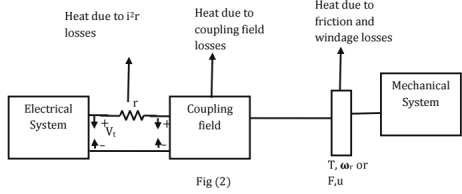
- e and i, on the electrical side and T(F) and ωr(u) on the mechanical side and associated with the coupling field
Note: If the torque, speed and the coupling field energy remains constant, the machine operates under steady-state conditions. - Under steady state conditions, there is no change in the energies stored in the magnetic field and the mechanical system.
- Under steady state conditions, Total output power + Loss of power due to various losses.
- For small energy changes, equ(2b) can be written in the differential form as d ,Welec = dWmech + d Wfld ...... (3)
- Now , the differential electrical energy input in time dt is Vt i.dt Ohmic losses = i2rdt
∴ Differential electrical energy input (Net) = d Welec
= Vti.dt - i2rdt
= (Vt - ir) i.dt
= eidt ......(4)
∴ Equation (3) becomes
Eidt = dWmech + d Wfid ....... (5) - Equation (5) is the energy balance equation, obtained by the use of the law of conservation of energy.
The analysis of energy conversion devices is based on the energy balance equation, in conjunction with faraday's laws of electromagnetic induction. - For electromechanical energy conversion process, the reaction of the coupling magnetic field on the electrical or mechanical system is necessary, since it is the link between the two systems.
- it may be thought of as link between the stationary and movable members.
- If the output is mechanical, then the coupling field reacts with the electrical system to absorb energy from it. This reaction is the "back" e.m.f, e.
- The coupling field absorbs energy proportional to e.i. From the electrical system and delivers energy proportional to t.ωr(or f.u) to the mechanical system.
- If the output is electrical, the coupling field must react with mechanical system to absorb mechanical energy.
- The output electrical energy is proportional to e.i. The conductor current i interacts with coupling magnetic field to produce a reaction torque opposite to the applied mechanical torque of the prime mover.
Summarizing
Motor: Coupling field absorbs energy proportional to e.i from the electrical system and delivers mechanical energy proportional to T. ωr to mechanical system.
Generator: Coupling field mechanical absorbs proportional [(reactive torque) x (speed)l from the mechanical system and delivers it as electrical energy output proportional to e.i to electrical system.
- The induced e.m.f, e and the torque, T are called the 'Electromechanical coupling terms.
- Electromechanical Energy conversion devices are slow-moving devices because of the inertia of the mechanical components.
- Therefore, the coupling field must be slowly varying.
- Electromagnetic radiation from the coupling field is negligible. Singly excited magnetic system
Electrical Energy Input: The fig shows a toroidal core excited form a single source.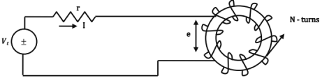
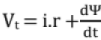
Applying KVL, w e have Vt = i.r + e ...... (1)
Where the reaction e.m.f., e is taken as a voltage drop in the direction of the current, i
∴  where ψ is the instantaneous flux linkages with the circuit.
∴ ....(2)
Multiply both sides by idt. We have,
∴ Vtidt = i2.rdt + idψ
i.e., (Vt - ir) idt = idψ
or e.i.dt = idψ
i.e., dWelec = eidt = idψ ....... (3)
- If the toroidal core is made of a ferro-magnetic material, most of the flux would be confined to the core.
- Let us assume that the flux ϕ links all the N-turns of the coil. Then ψ = N.ϕ so that dWelec = idψ = (iN) dϕ = Fdϕ ....(4)
Where ϕ is the instantaneous flux and F is the instantaneous m.m.f., - From the eq(4), it is obvious that the flux linkages must change in order that the toroid may extract energy from the supply.
- As the flux linkages change, the reaction e.m.f., e is generated.
- The flow of the current against e causes the extraction of energy from the source (i.e., the electrical system)
Magnetic Field Energy Stored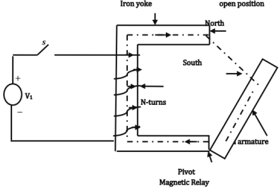
- A simple magnetic relay is shown in the fig
- Initially, when S is in open position, the armature (movable member) is in the open position.
- On dosing the switch S, a current I flows through the coil, setting up a flux.
- The magnetic field set up creates a North pole (on yoke) and a south pole (on the armature) as shown.
- Therefore a magnetic force of attraction acts on the armature.
- The armature has a tendency to move towards the yoke, which shortens the air gap.
- If, however, the armature is NOT allowed to move, the mechanical work done, sWmech = 0
- ∴ From the energy - balance equation we have dWelec = 0+dWfld
- Thus, when the movable part of any physical system is kept fixed, the entire electrical energy is stored in the magnetic field.
∴ dwfld = dwelec = idψ = fdϕ ....(5) - If the initial flux is zero , the magnetic field energy stored , wfld in establishing a flux ϕ1 is given by
 Note: i must be expressed in terms of ψ and F in terms of ϕ.
 - When the armature is held in the open position, most of the m.m.f. is consumed in the air saturation may not occur.
- Then ψ varies linearly with i and ϕ varies linearly with F.
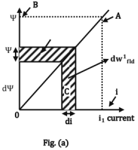
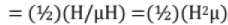
 Referring to Fig(a),
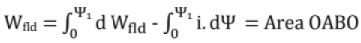
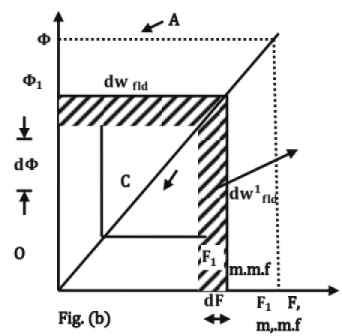
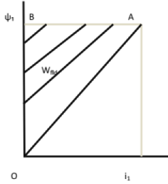
Referring to Fig(b),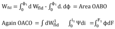
- Area OACO is called the co-energy.
Note: Co-energy has NO physical significance. It is useful in calculating the mechanical forces. - With no magnetic saturation
Area OABO = area OACO i.e.,
Also, = area OABO + area OACO
= Area OCABO = ϕ1F1 = ψ1i1. - In general, for a linear magnetic circuit.
- Other forms:
m.m.f., F = ϕs, wehre s is reluctance.
= ϕ/^, where ^ is permeance.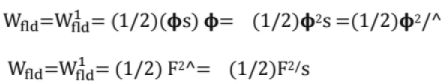
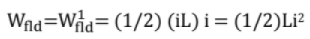
- Also, The self inductance, L = ψ/i
- Magnetic stored energy density, Wfld

= (1/2)H.B. Joules /m3
For a linear magnetic circuit,
Note: Field energy approach serves as the physical basis for the generalizes theory of electrical machines (since the Field can be expressed in terms of the circuit parameter, L)
Mechanical Work Done: Let us once again consider the magnetic relay.
When the Movable End of the Armature Is Held in the Open Position
- Before the switch S is closed, i = 0 and hence ψ = 0
- On dosing the switch, the current increases from zero to
 where r is the resistance of the coil.
 - The flux linkages increases from 0 to ψ1
- Since the magnetic circuit is linear (most of the e.m.f., is used in the air gap), the ψ - I relation is linear as shown in the fig (a) bellow. Energy stored in the magnetic field, Wfld = Area OABO
When the Movable End of the Armature Is In The Closed Position (l.E. It IS IN Constant With the Yoke)
- The air gap is zero
- The reluctance of the magnetic path is very much reduced.
- Since the final value of the exciting current is i1 = (Vt / r), the mmf is the same .So , the flux linkages are ψ2 > ψ1
- Magnetic saturation may also set in ∴ the ψ-I relation is as shown in fig(b) Energy stored in the magnetic field.
WFld = Area OCDO
During the Movement of the Armature: When the armature is in the open position, the exciting current sets up a magnetic field. Flux linkages are ψ1.
- Due to force of attraction, the movable end of the armature begins to move towards the yoke, shortening the air-gap
Because of the shortening of the air gap, the reluctance decreases and hence the flux linkages increases from ψ1. - When the armature is finally in the closed position, the flux linkages ψ2.
- Thus, during the movement of the armature, the flux linkages are changing from initial value ψ1.
- The change in the flux linkages induces a counter e.m.f., in the coil, which opposes the flow of current.
Therefore 
Here, we have to use the coil impedance (not the resistance, as the flux linkages are changing)
The magnitude of the counter e.m.f depends on how FAST the armature is moving from open position to closed position.
Before considering the actual movement of the armature which can neither to be considered to be too slow or too fast (instantaneous), let us consider two extreme cases; viz,
(i) Very slow movement
(ii) Very fast movement
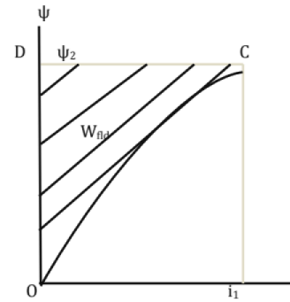
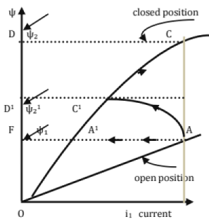
Slow Movement: When the armature is in the open position, exciting current= i1, flux linkages = ψ1 operating point is A.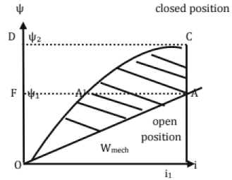
- Since the armature movement is assumed to be slow, the counter e.m.f. induced in the coil = (ψ1 - ψ2), time may be neglected.
- Therefore the current remains substantially constant, during the movement of armature also.
- When armature in closed position, exciting current = i1, flux linkages = ψ2 (> ψ1) operating point is C.
- Since the current i1 is throughout, the operating point moves along the vertical line AC and finally reaches new operating point C.
- Since there is movement of armature, some mechanical work is done. It can be calculated as follows.
- Change in the stored energy of the magnetic field , Wfld , as the operating point (open position ) to C(closed position) is Wfld = [Magnetic energy stored in closed position] - [Magnetic energy stored in open position]
= Area OA1CDFO - Area OAA1 FO - Since there is change in flux linkages. Electric energy input during the change,
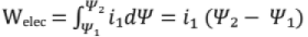
= Area A C DFA1 A - From the energy - balance equation
Welec = Wfid + Wmech.
i.e, Area ACDFA 1A = Area OA1CDFO - Area OAA1FO + Wmech.
∴ Wmech = Area [A C DFA1 A + OAA1 FO] - Area [OA1CDFO]
= Area OACDFO - Area OA1CDFO
= Area OACA10(i.e the hatched area in the figure)
= Area enclosed by the magnetization curve at the closed position and the magnetization curve at the open position and ψ-1 locus during the slow movement of the armature. Thus,
The mechanical work done is equal to the area enclosed between the two magnetization curves at open and closed positions and ψ-1 locus during movement of the armature. - During the slow movement of the armature, a part of electrical energy input is stored in the magnetic field and remaining is output as mechanical energy.
- If saturation is neglected, half of the electrical energy input is stored in the magnetic field and other half is output as mechanical.
II. Instantaneous Movement of the Armature
When the armature in open position, the operating point is A corresponding to an exciting current of U and flux linkages ψ1.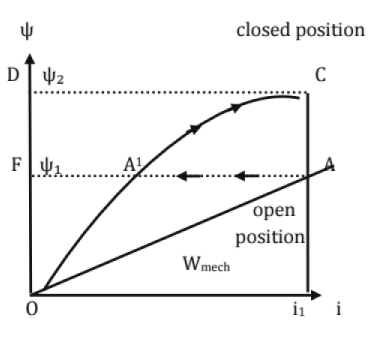
- The final operating point is to be C corresponding to the same an exciting current of i1 and flux linkages ψ2, when the armature is in closed position.
- We know that according to Constant flux linkage theorem, the flux linkage with an inductive circuit can't change suddenly.
- Here as the armature is assumed to be moved from open position to closed position instantaneously, the flux changes ψ1 cannot change instantaneously but should remain constant at ψ1 during the movement of armature.
- Therefore the operating point moves from A to A1 along the horizontal line.
- However, the movement it reaches the closed position, the operating point A1 is to be on the closed position magnetization curve.
- The current I corresponding to A1 is less than ii the final value. Therefore the operating point moves from A1 to C along the closed position magnetization curve and flux linkages are ψ2.
- During the instantaneous movement of armature,
(i) change in the stored magnetic energy Area OA1FO - Area OAA1 FA and
(ii)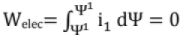 since flux linkage remain constant.
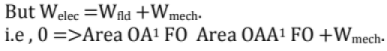
∴ Wmech = Area OAA1 FO - Area OA1 FO
= Area GAA1 O
= Area enclosed between the 2 magnetization curves and ψ-1 locus during instantaneous armature movement.
ThusDuring fast armature movement, electrical energy input = 0 Mechanical energy output = reduction in stored magnetic energy.
Transient Energy of Armature
- The actual movement is neither too slow nor too fast (instantaneous).
- So, neither the current remain constant nor flux linkages remain constant.
- Current decreases (due to back e.m.f.) and flux linkages will increase (due to reduced air gap).
- Initially, the armature movement is slow, but it becomes faster as it nearing the closed position.
- The transient ψ-1 locus is AC1 C as shown in figure.
- The operating point moves from A to C1 during the armature movement.
- C1 corresponds to closed position.
- Since final current is to be i1, the operating point moves from C1 to C along the closed position magnatization curve.
- During the time, the armature moves from open (Point A) to dosed (Point C1) position. [beyong C1 there is no movement of the armature and hence no mechanicle work is done
(i) Change in the magnetic stored energy,
Wfld = area OA1 C1 D1 FO - area OA A1 FO
(ii)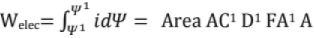
But Welec = Wfld +Wmech.
i.e Area AC1 D1 FA1 A = area OA1 C1 D1 FO — area OA A1 FO + Wmech
Wmech = Areas[AC1 D1 FA1A +OAA1 FO] - area[OA1 C1 D1 FO]
= Area OAC1 D1 FO - area OA1 C1 D1 FO
= Area OA C1 A1O
= Area enclosed between 2 magnatization curves and ψ-1 locus during the transient movement of armature.
Caluculation of Mechanical Force: The magnetic force is not constant but increases as the gap length decreases so the avarage magnetic force is calculated as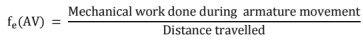

Principle of Virtual Work
- It is method of determining magnetic force
- A differential movement of armature dx is imagined in the direction of fe
- dx need not to be real and hence it is called virtual displacement.
- fe.dx is called virtual work.
- The effect of virtual displacement on the energy balance is investigated to obtain the magnitude and direction of fe.
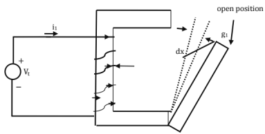
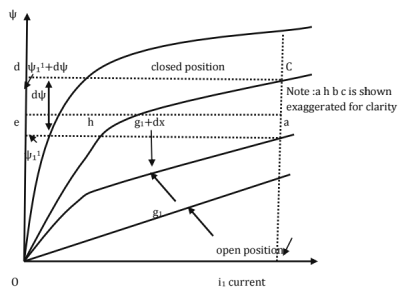
NOTE: in case of ratatable members, the virtual displacement is dθ. - The armature is at an intermediate position and gap lengh is g1 from the open position. A virtual displacement dx is assumed in the direction of magnetic force (this corresponds to reduction in the gap lengh)
- The magnetization curve curves corresponds to g1 and (g1+dx) are shown
- The transient locus is abc
Position g1 :operating point is a current i1 ;flux linkages
Position g1 + dx operating point is current i1 ;flux linkages
(i) Mechanical work done during virtual displacement dx is
= Area 0 a b h O
= fe.dx
Now area of Area 0 a b h O = Area 0 a b h O + area of Aabh
area of Δ abh ≥ 0 as dx ≥ 0 Thus, the movement of the armature is assumed to be instantaneous
i.e the armature movement over the virtual displacement dx may be taken as instantaneous (constantψ)
In both the cases, the final operating is at (g1+dx) must be only c only.
Now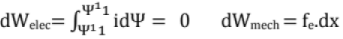 ∴ from the energy balance equation
0 = fe.dx + dWfld at constant ψ
∴ fe.dx = - dWfld at constant ψ
Thus the mechanical is work done at the expense of the field energy stored if at constant ψ.
Hence, the negative sign before d Wfld
Also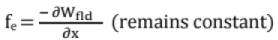
Thus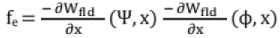
In the above expression for mechanical force of field origin, ψ, φ are independent variables.
Since voltage α dψ/dt, this expression for fe is applicable for voltage control system - Again area OabhO = area OacbhO - area of Aabc
≈ area OcbhO as dx → 0
i.e the armature movement over the virtual displacement may be taken as slow (constant current). The operating point moves VERTICALLY from a to c.
Here, d Now Area acdea = area Ojcdo - area OjaeO= [(magnetic stored energy + co -energy) at position g1+dx] — [(magnetic stored energy + co - energy) at position g1]
i.e area acdea = differential increase in field energy + differential increase in cp-energy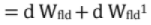
But area acdea also represents d Welec = i1dψ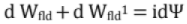
But
From the energy balance equation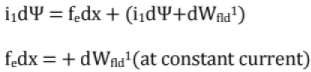
Thus during the virtual displacement, the co - energy increases and hence the positive sign before dWfld1.
Note: Wfld1 must be expressed in terms of (l, x) or (F, x)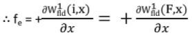
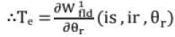
for angular movements of armature, the electromagnetic torque, Te is given by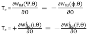
The above expression for force is applicable to a system in which the current is an independent variable.
It is applicable to a current controlled system.
Conclusion: Any physical device will develop a force or torque, if its magnetization curve is affected by a differential displacement of its movable (or rotatable) part, the other part remaining fixed.
Note
(i) The above equations are all applicable whether or not the magnetic circuit is saturated.
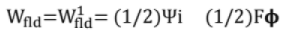
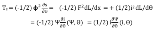
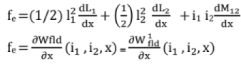
(ii) If saturation is neglected, the ψ-I and the F-ϕ relations are linear. Then
(a) Wfld = (1/2)2s fc = (-1/2) ϕ2 ds/dx
(b) Wfld = (1/2)F2^-(1/2)i2L
fe = (1/2)F2d^/dx = (1/2) i2dL/dx
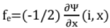
(c) Wfid= (1/2)ψ. If i is expresses in terms of ψ and x,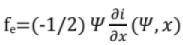
- if ψ is expressed in terms of i and x
- similarly, for the electromagnetic torque, Te, we have
Important:
The electromagnetic force or torque acts in such a direction so as to tend to
(i) Decrease the magnetic stored energy at constant ψ or ϕ
(ii) Increase both field energy stored and co-energy at constant current or m.m.f.
(iii) Decrease the reluctance.
(iv) Increase the permeance and inductance.
(v) Decrease the current i at constant flux linkages ψ or increase ψ at constant I,
Note: AH the equations derived are applicable to fields produced by permanent magnets since fe and Te do not depend upon the source of the field (but only on magnetic field)
Alternative Approach
- Wfld is a function of the flux linkages ψ or flux ϕ
- The field energy is mainly stored in the air - gap.
- If the air-gap varies, then the distance x measured from the OPEN position also varies.
- As x varies, field energy stored varies
∴ Wfld is a function of two independent variables ψ and x (or ϕ And x) - Mechanical work done in deferential movement dx in the direction of the force fe is d Wmech = fe. dx
- Furthur, d Welec = I d ψ
∴ From the energy balance equation.
id ψ = d Wfld (ψ, x) + fe dx
∴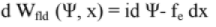 ...(A)
 - The above equation is more general.
- For ex, if the armature is assumed stationary,
dx = 0 and hence
d Wfld = id ψ - since Wfld is a function of ψ and x,
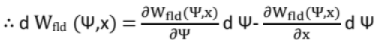 ...(B)
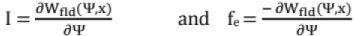
 - Comparing the coefficients of like terms in equation (A) and (B)
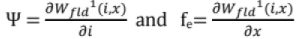
- Again, the co-energy
 depends on i and x
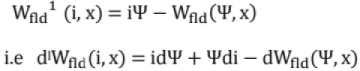
i.e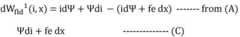
since is a depends on i and x,
- On comparing (C) and (D)
- Examples of singly excited magnetic systems
(i) Electromagnetic.
(ii) Relays
(iii) Moving iron instruments
(iv) Reluctance motors ,etc
Doubly Excited Magnetic Systems
- Most of the electromagnetic energy conversation devices are multiply excited systems.
- A doubly excited magnetic system is excited by two independent sources of excitation. Ex: Synchronous machine, loud speakers, Tachometers, D.C shunt machine etc
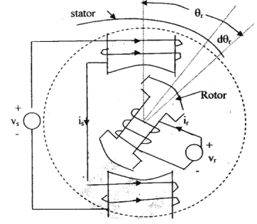
- The figure shows the simple model of a doubly excited system.
- It consists of
(i) Stator iron
(ii) Rotor iron
Both of the SALIENT pole type. - Source 1 energies the stator with Ns turns.
- Source 2 energies the stator with Nr turns.
- The m.m.f.s produced by the stator and rotor windings are in the same direction.
- So, the magnetic torque Tc is in the counter clockwise direction
- The magnetic saturation and hysteresis are neglected in the following treatment.
- The differential electrical energy input from both the sources,
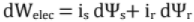
where the ψ's are the instantaneous flux linkages - Since magnetic saturation is neglected .
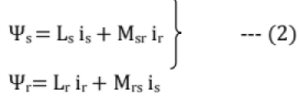
Where Ls and Lr are the self inductances of the stator and rotor windings, respectively;
and Msr = Mrs = mutual inductance between the windings. - Initially, the space angle between rotor and stator axes is θr. is and ir are assumed to be zero.
- On energizing the windings, both the winding currents increases to is and ir, respectively.
- If the rotor is not allowed to move,
- d Wmech = 0
dWelec = 0 + dWfld
Thus, with the rotor held fixed, all the electric energy input is stored in the magnetic field From eq (1);
.............. 95........ -
dWfld = dWelec = is dψs+ ir dψr
= is d ( Ls is + Msr ir) + ir d (Lr ir + Mrs is) .... (3)
Also, we known that Ls= cc/Ss and
And Msr = Mrs = Ns Ns/ Ssr
Where Ss = reluctance seen by the stator flux
Sr = reluctance seen by the rotor flux
Ssr = reluctance seen by the resultant of stator and rotor fluxes
Now equation (3), we have
dWfld = is [dLs is + Lsdis + d Msr ir + Msr d ir] + ir [dLrir + Lrdir+ d Mrs is + Mrs dis] — (4) - Since the rotor is not allowed to move, the reluctances and the inductances are constant.
∴ dLs = 0, dLr = D ; d Msr = d Mrs = 0
∴ Equation (4) because,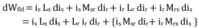

Therefore, the magnetic field energy stored in establishing the currents from 0 to is and ir, is given by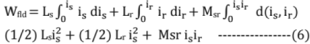
- For obtaining the torque, principle of virtual work is used
- A virtual displacement dθr is assumed in the direction of Te.
- Now, all the reluctances and the inductances vary.
∴ During virtual displacement dθr
- The diffenrential magnetic energy stored,
 and the mechanical work done, dWmech = Te. dθr ...(3)
From the energy balance equation (1) (2) + (3) - On simplification
 ...(4)
NOTE
- Te is independent of the changes in the currents (since di5anddirare absent)
Te is depends on (i) the instantaneous value of currents
And (ii) angular rate of change of inductances. - if dWfld is differentiated with respect to the space angle θr (with is hand ir treated constant), then also equation (4) is obtained
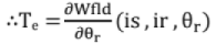
i.e, Torque can be obtained from the space derivation of field energy expression, where it is expressed in terms is, ir, and θr - with constant currents

For a linear magnetic circuit,
- Magnetic energy stored at constant currents = mechanical work done.
For a linear magnetic system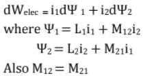
6. Spedal Machines
Servomotors
- These motors are used in feed - back control systems as output actuators.
- They have low rotor inertia and, therefore, they have a high speed of response.
- Servomotors are widely used in radars, computers, robots, machine tools, tracking and guidance systems, process controllers etc.
DC Servomotors
- DC servomotors are separately excited dc motors or permanent magnet dc motors.
- The speed of dc servomotors is normally controlled by varying the armature voltage.
- The armature of a dc servomotor has a large resistance, therefore, the torque - speed characteristics are linear and have a large negative slope. It has a fast torque response because torque and flux become decoupled.
AC Servomotors
Two - Phase AC Servomotor
- The stator has two distributed windings which are displaced from each other by 90 electrical degrees. One winding, called the reference or fixed phase, is supplied from a constant voltage source Vm ∠ 0°. The other winding, called the control phase, is supplied with a variable voltage of the same frequency as the reference phase, but is phase displaced by 90 electrical degrees (may not be exactly 90°).
- The speed and torque of the rotor are controlled by the phase difference between the control voltage and the reference phase voltage. The direction of rotation of the rotor can be reversed by reversing the phase difference, from leading to lagging (or vice versa), between the control phase voltage and the reference phase voltage.
Three - Phase AC Servomotors
- A 3 - phase squirrel - cage induction motor is normally a highly nonlinear coupled circuit device.
- Recently, it has been used as a linear decoupled machine by using a control method called vector control or field - oriented control. This result in high - speed response and high - torque response.
Comparsion of Servomotors with Conventional Motors
- Servomotors produces high torque at all speeds including zero speeds.
- They have low rotor inertia; therefore their direction of rotation can be reversed very quickly.
- A servomotor can withstand higher temperature at lower speeds or zero speed.
- The rotor resistance is very high to make characteristic curve linear.
Stepper (or Stepping) Motors
- The stepper or stepping motor has a rotor movement in discrete steps.
- The angular rotation is determined by the number of pulses fed into the control circuit.
There are three most popular types of rotor arrangements:
- Variable reluctance (VR) type
- Permanent magnet (PM) type
- Hybrid type, a combination of VR and PM
Step Angle
The angle by which the rotor of a stepper motor moves when one pulse is applied to the (input) stator is called step angle. This is expressed in degrees. The resolution of positioning of a stepper motor is decided by the step angle.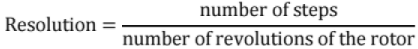
Higher the resolution, greater is the accuracy of positioning of objects by the motor.
Variable Reluctance (VR) Stepper Motor
The principle of operation of a variable reluctance (VR) stepper motor is based on the property of flux lines to occupy low reluctance path.
Single - Stack Variable Reluctance Motor
- A variable reluctance stepper motor has salient - pole (or teeth) stator.
- The stator has concentrated windings placed over the stator poles (teeth). The number of phases of the stator depends upon the connection of stator coils.
- When the stator phases are excited in a proper sequence from dc source with the help of semiconductor switches, a magnetic field is produced.
- The ferromagnetic rotor occupies the position which presents minimum reluctance to the stator field.
The magnitude of step angle for any PM of VR stepper motor is given by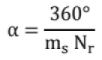
where
α = step anlge
ms = number of stator phases or stacks
Nr = number of rotor teeth (or rotor poles)
The step angle is also expressed as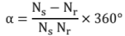
where Ns = stator poles (or stator teeth)
Multi - Stack Variable Reluctance Stepper Motor
- A multi - stack (or m - stack) variable reluctance stepper motor can be considered to be made up of m identical single - stack variable reluctance motors with their rotors mounted on a single shaft. The stators and rotors have the same number of poles (or teeth) and, therefore, same pole (tooth) pitch.
- For a m - stack motor, the stator poles (o r teeth ) in all m stacks are aligned, but the rotor poles (teeth) are displaced by 1/m of the pole pitch angle from one another.
- All the stator pole windings in a given stack are excited simultaneously and, therefore, the stator winding of each stack forms one phase.
Let Nr be the number of rotor teeth and m the number of stacks or phases.
Then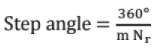
Permanent Magnet (PM) Stepper Motor
The permanent - magnet (PM) stepper motor has a stator construction similar to that of the single - stack variable reluctance motor. The rotor is cylindrical and consists of permanent - magnet poles made of high retentivity steel.
Hybrid Stepper Motor
The main advantage of the hybrid stepper motor is that if the motor excitation is removed, the rotor continues to remain locked into the same position as before removal of excitation. This is due to the fact that the rotor is prevented to move in either direction by the detent torque produced by the permanent magnet.
Advantages of Hybrid Stepper Motors
- Small step length and greater torque per unit volume.
- Provides detent torque with windings de - energized.
- High efficiency at lower speeds and lower stepping rates.
Disadvantages of Hybrid Stepper Motors
- Higher inertia and weight due to presence of rotor magnet.
- Performance affected by change in magnetic strength.
- More costly than variable reluctance stepper motor.
Applications of Stepping Motors
Stepper motors are widely used In numerical control of machine tools, tape drives, floppy disc drives, printers, X - Y plotters, robotics, textile industry, integrated circuit fabrication, electric watches etc. the other applications of stepper motors are in spacecrafts launched for scientific explorations of planets. Stepper motors are also used in the production of science fiction movies. These motors also find variety of commercial, medical and military applications and will be increasingly used in future.
FAQs on Chapter 11 - Machines (Part-3) - Mechanical Engineering
| 1. What are the principles of electro mechanical energy conversion? |  |
| 2. How does electromagnetic induction play a role in electro mechanical energy conversion? | |
| 3. What is the significance of electromagnetic attraction and repulsion in electro mechanical energy conversion? | |
| 4. How do electromagnetic forces act on conductors in electro mechanical energy conversion? | |
| 5. Which electrical machines utilize the principles of electro mechanical energy conversion? | |


Objective type Questions
,Sample Paper
,mock tests for examination
,Chapter 11 - Machines (Part-3) - Mechanical Engineering
,past year papers
,Extra Questions
,Viva Questions
,Chapter 11 - Machines (Part-3) - Mechanical Engineering
,Previous Year Questions with Solutions
,Free
,video lectures
,Chapter 11 - Machines (Part-3) - Mechanical Engineering
,Summary
,shortcuts and tricks
,study material
,Important questions
,Semester Notes
,ppt
,practice quizzes
,MCQs
,Exam
;


Chapter 11 - Machines (Part-3) Free PDF Download
Importance of Chapter 11 - Machines (Part-3)
Chapter 11 - Machines (Part-3) Notes
Chapter 11 - Machines (Part-3) Mechanical Engineering Questions
Study Chapter 11 - Machines (Part-3) on the App
|
© EduRev
|
Education Revolution
|


|


