Basic Electrical Components: Introduction | Sensor & Industrial Instrumentation - Electronics and Communication Engineering (ECE) PDF Download
Introduction
Resistors, capacitors, and inductors—these are the three basic passive elements used in electrical circuits, either as individual devices or in combination. These elements are used as loads, delays, and current limiting devices. Capacitors are used as dc blocking devices, in level shifting, integrating, differentiating, filters, frequency determination, selection, and delay circuits. Inductive devices can be extended to cover analog meter movements, relays, audio to electrical conversion, electrical to audio conversion, and electromagnetic devices. They are also the basis for transformers and motors.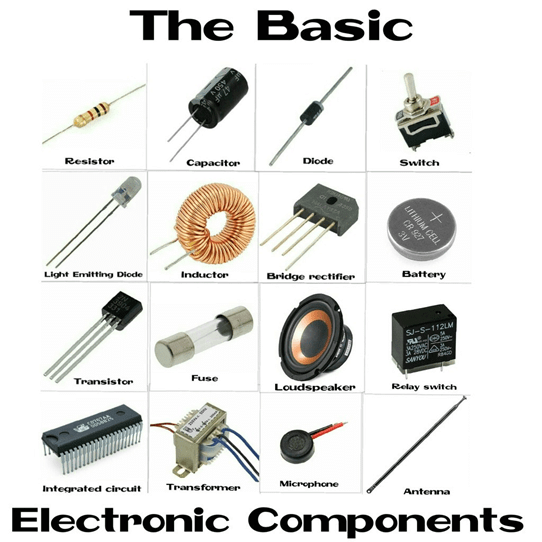
Circuits with R, L, and C
Passive components are extensively used in ac circuits for frequency selection, noise suppression, and so forth, and are always present as parasitic components, limiting signal response and introducing unwanted delays. These components also cause phase shift between voltages and currents, which has to be taken into account when evaluating the performance of ac circuits.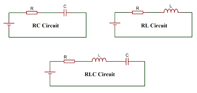 (i) Voltage Step Input
- When a dc voltage is applied to the series resistor-capacitor circuit shown in Figure 3.1(a) a current flows in the elements, charging the capacitor. Figure 3.1(b) shows the input voltage step, the resulting current flowing, and the voltages across the resistor and the capacitor. Initially, all the voltage is dropped across the resistor. Although current is flowing into the capacitor, there is no voltage drop across the capacitor. As the capacitor charges, the voltage across the capacitor builds up exponentially, and the voltage across the resistor starts to decline, until eventually the capacitor is fully charged and current ceases to flow. The voltage across the capacitor is then equal to the supply voltage, and the voltage across the resistor is zero.
- It should be noted that the current flowing through the resistor and into the capacitor is the same for both components, but the voltages across each component are different. That is, when the current flowing in the resistor is a maximum, the voltage across the resistor is a maximum, given by E = IR, and the voltage is said to be in phase with the current. In the case of the capacitor, the voltage is zero when the current flowing is a maximum, and the voltage is a maximum when the current is zero. In this case, the voltage lags the current, or there is a phase shift between the voltage and the current of 90°. The voltage across the capacitor builds up exponentially, at a rate determined by the values of the resistor and the capacitor.
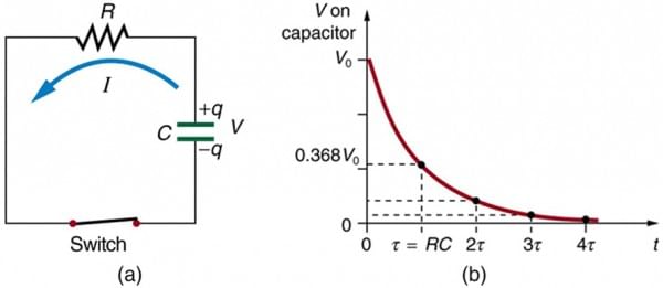 Figure 3.1 (a) Input voltage transient to a circuit with resistance and capacitance, and (b) associated waveforms.
- When a dc voltage is applied to a series inductance circuit resistance, as shown in Figure 3.2(a) a current will build up, Figure 3.2(b) shows the input voltage step, the resulting current buildup, and the voltages across the resistor and the inductor the inductance will initially appear as a high impedance preventing current from flowing. The current will be zero, the supply voltage will appear across the inductance, and there will be zero voltage across the resistor. After the initial turn-on, current will start to flow and build up, the voltage across the resistor will increase, and then start to decrease across the inductance. This allows the current to build up exponentially, until the current flow is limited by the resistance at its maximum value and the voltage across the inductance will be zero. The effects are similar to those that occur when a dc voltage is applied to a series R.C. network. The voltage and current in the resistor are in phase, but in the inductor are out of phase. That is, in this case, the voltage appears across the inductance before the current starts to flow, and goes to zero when the current is at its maximum, so that the voltage leads the current, and there is a phase shift between the voltage and the current of 90°. The voltage across the resistor increases exponentially, at a rate determined by the value of the inductance and resistance.
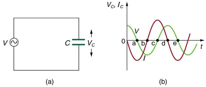 Figure 3.2 (a) Input voltage transient to a circuit with resistance and inductance, and (b) associated waveforms.
(ii) Time Constants
In an RC network when a step voltage is applied, as shown in Figure 3.1(a), the voltage across the capacitor is given by the equation [1]:
EC = E(1− e −t/RC) .........(3.1)
where EC is the voltage across the capacitor at any instant of time, E is the source voltage, t is the time (seconds) after the step is applied, R is in ohms and C is in farads.
Conversely, after the capacitor is fully charged, and the step input voltage is returned to zero, C discharges and the voltage across the capacitor is given by the equation:
EC = Ee−t/RC
Similar equations apply to the rise and fall of currents in the inductive circuit shown in Figure 3.2(a).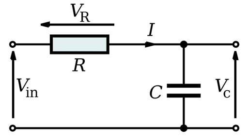 (ii) Sine Wave Inputs
When an ac sine wave is applied to C, L, and R circuits, as shown in Figure 3.3(a) the same phase shift between voltage and current occurs as when a step voltage is applied. Figure 3.3(b) shows the relationship between the input voltage, the current flowing and the voltage across C, L, and R as can be seen. In resistive elements, the current and voltage are in phase; in capacitive circuits, the current leads the voltage
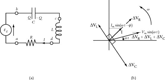 Figure 3.3 (a) Series R, C, and L circuits, and (b) waveforms and phase relations in a series circuit.
by 90° (Figure 3.1); and in inductive circuits, the current lags the voltage by 90° (Figure 3.2).
Since the voltages and the currents are not in phase in capacitive and inductive ac circuits, these devices have impedance and not resistance. Impedance and resistance cannot be directly added. If a resistor, capacitor, and inductor are connected in series as shown in Figure 3.3(a), then the same current will flow through all three devices. However, the voltages in the capacitor and inductor are 180° out of phase and 90° out of phase with the voltage in the resistor, respectively, as shown in Figure 3.3(b). However, they can be combined using vectors to give:
E2 = V2R + (VL - VC)2 .......(3.5)
where E is the supply voltage, VR is the voltage across the resistor, VL is the voltage across the inductor, and VC is the voltage across the capacitor.
The vector addition of the voltages is shown in Figure 3.4. In Figure 3.4(a), the relations between VR, VL, and VC are given. VL and VC lie on the x-axis, with one positive and the other negative, since they are 180° out of phase. Since they have opposite signs, they can be subtracted to give the resulting VC − VL vector. VR lies at right angles (90°) on the y-axis. In Figure 3.4(b), the VC − VL and VR vectors are shown with the resulting E vector, which, from the trigonometry function, gives (3.5). The impedance (Z) of the ac circuit, as seen by the input is given by: ........(3.6)
where XC = 1/2πfC, which is the impedance to an ac frequency of f hertz by a capacitor C farads, and XL = 2πfL, which is the impedance to an ac frequency of f hertz by an inductance of L henries.
The current flowing in the circuit can be obtained from Ohm’s Law, as follows:
I = E/Z ............(3.7)
|
26 videos|28 docs|29 tests
|
FAQs on Basic Electrical Components: Introduction - Sensor & Industrial Instrumentation - Electronics and Communication Engineering (ECE)
| 1. What are basic electrical components? |  |
| 2. What is the purpose of a resistor in an electrical circuit? |  |
| 3. How does a capacitor work in an electrical circuit? |  |
| 4. What is the role of an inductor in an electrical circuit? |  |
| 5. How does a diode function in an electrical circuit? |  |


