Capacitive Transducers | Sensor & Industrial Instrumentation - Electronics and Communication Engineering (ECE) PDF Download
Capacitive Transducers
The capacitive transducers work on the fundamental principle of electrical capacitance. The capacitance C of a system depends on the dielectric medium used and properties of a capacitive system.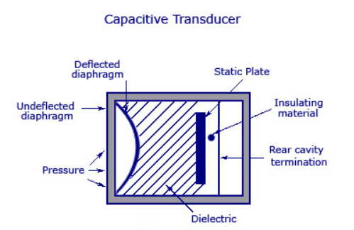 The important capacitances used in the capacitive transducers are:
1. Parallel plate capacitor: The capacitance of a parallel plate capacitor is given by,
where ε = εo εr, εo = 8.85 x 10⁻¹² F/m
εr = Relative permittivity of material
A = Cross-sectional common area of plates
d = Plate separation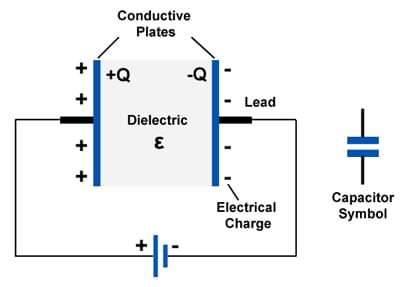 Fig. 8.42 Parallel plate capacitor
The arrangement is shown in the Fig. 8.42.
By using simple methods, the capacitance of the capacitor can be varied and change in its value can be used for transduction in a transducer.
2. Composite capacitor: This capacitance consists of more than one dielectric medium in between the plates as shown in the Fig. 8.43. It consists of three layers of dielectrics having relative permittivities ε1, ε2 and ε3. The layers having thicknesses d1, d2 and d3. The capacitance of a system is given by.
 Fig. 8.43 Composite capacitor
The system creates the effect of three capacitances connected in series.
3. Cylindrical capacitor: In this system, the plates are cylindrical separated by a dielectric as shown in the Fig. 9.21.
Let r = Outer radius of inner cylinder
R = Inner radius of outer cylinder
Then its capacitance is given by,
and I is length of the cylinders.
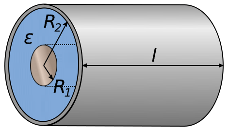 Fig. 9.21 Cylindrical capacitance
Variation in Capacitance
To have capacitive system to be used as a sensor, it is necessary to change the value of capacitance proportional to the action to be measured or detected. Such a variation of capacitance is achieved in four ways.
1. Change of distance: The capacitance C depends on separation between the plates. Thus by varying the distance of separation, C can be varied. The system is shown in the Fig. 9.22 (a) in which distance is varied by keeping one plate fixed and other plate moving. As the distance increases from d to d' the capacitance decreases from C to C'. Fig. 9.22 (a) Change in separation
Another method of varying the distance is employing cantilever spring plate as shown in the Fig. 9.22 (b).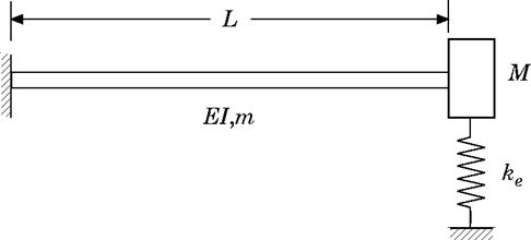 Fig. 9.22 (b) Use of cantilever spring plate
2. Change in common plate area: By keeping the one plate moving and changing its position parallel to the other plate, common plate area can be varied. This is shown in the Fig. 9.23. By varying area A, the capacitance can be varied.
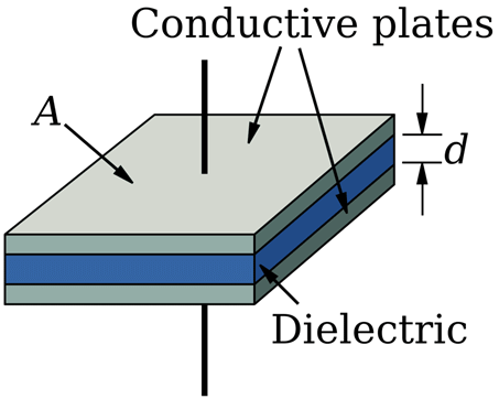 Fig. 9.23 Change in common plate area
This method is suitable in the measurements of rotational displacement. The arrangement is employed in the form of slotted rotor and stator as shown in the Fig. 9.24 (b). As the rotor plates of the capacitor are rotated, the capacitance varies proportional to the angular displacement of the rotor plates. This method can be used to measure the torques. Fig. 9.24 (a) Change in area (b) Measurement of angular displacement
3. Change in dielectric: By inserting a slab of variable permittivity, the capacitance can be varied. Introduction of slab of variable permittivity gives rise to a composite capacitor. This is shown in the Fig. 9.25. This method is used in capacitance type level meter.
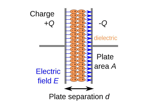 Fig. 9.25 Change in dielectric
4. Using quartz diaphragms: In some cases the two silvered quartz diaphragms are used as shown in the Fig. 9.26. Depending upon the pressure the displacement of these diaphragms vary and hence the capacitance of the system gets varied. This method is used in capacitive pressure transducers.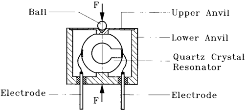 Fig. 9.26 Use of quartz diaphragms
 |
Test: Transducers- 3
|
Start Test |
Capacitance Type Level Meter
The capacitive transducer using the method of change in dielectric is used for the measurement of the liquid levels. The Fig. 9.27 shows the capacitance type level meter.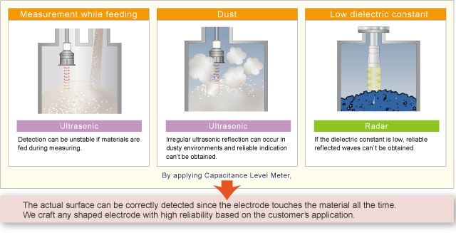 Fig. 9.27 Capacitance type level meter
It is uses concentric cylindrical capacitor. The two plates are cylindrical using the dielectric material with a permittivity ε1. Most of the times, this dielectric is an air with εr = 1 and ε = ε0. The outer cylindrical plates have holes at the bottom through which passage of liquid is possible between the plates.
Let r = Outer radius of inner cylinder
R = Inner radius of outer cylinder
d = Height of tank
d2 = Level of liquid in tank
ε2 = Permittivity of liquid
As the liquid level d2 changes, the composite capacitor formed experiences change in its value. The value of the capacitance is given by,

Thus, change in the liquid level causes the change in the capacitance measured between the cylinders.
This change in capacitance is detected by some other circuit with which the electrical signal proportional to the liquid level can be obtained.
Capacitive Pressure Transducer
The capacitive pressure transducer is based on the principle that when the distance between the two parallel plates changes, capacitance of the parallel plate capacitor changes. The capacitive pressure transducer is as shown in the Fig. 9.28.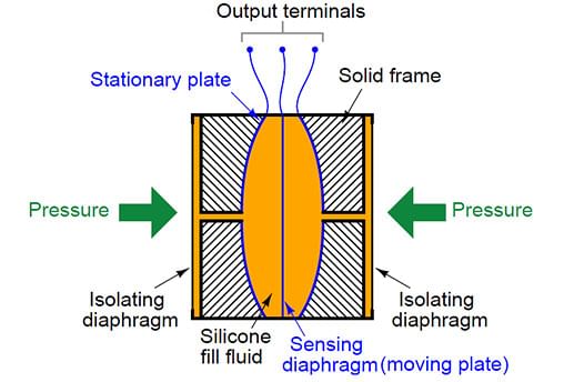 Fig. 9.28 Capacitive pressure transducer
In capacitive pressure transducer diaphragm acts as one of the plates of a two plate capacitor while other plate is fixed. The fixed plate and the diaphragm are separated by a dielectric material. When the force is applied to the diaphragm, it changes its position from initial static position obtained with no force applied. Due to this, the distance of separation between the fixed plate and the diaphragm changes, hence the capacitance also changes. The change in the capacitance can be measured by using any simple a.c. bridge. But practically the change in capacitance is measured using an oscillator circuit where capacitive transducer is part of that circuit. Hence when capacitance changes, the oscillator frequency changes accordingly. In this way, by using capacitive transducer, applied force can be measured interms of change in the capacitance.
 |
Download the notes
Capacitive Transducers
|
Download as PDF |
Advantages and Disadvantages of Capacitive Transducers
The advantages of the capacitive transducers are as follows:
- The force requirement is very small, hence the power required to operate is small and very useful in small systems.
- They are highly sensitive.
- They have good frequency response and very high input impedance, so loading effects are minimum.
- They are useful in the applications where stray magnetic fields affect performance of the inductive transducers.
The disadvantages of the capacitive transducers are as follows:
- Proper insulation is required between the metallic parts of the capacitive transducers.
- The stray capacitances affect the performance of the transducer. It can be overcome by properly earthing the frame of the transducer.
- They show non-linear behaviour due to edge effects and stray electric fields. These can be eliminated by using guard rings.
- Due to long leads and the cables used, loading effect makes low frequency response poor and reduces sensitivity.
- For low value capacitances (of the order of pico-farads) the output impedance tend to very high value which causes loading effects.
|
23 videos|24 docs|29 tests
|


