Theodolite, Compass & Traverse Surveying | Geomatics Engineering (Surveying) - Civil Engineering (CE) PDF Download
Traverse Surveying
Latitude and Departure
The latitude and departure of the line AB of length l and reduced bearing θ are given by
L = +lcosθ
D = lsinθ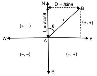
Latitude: Projection of a line on N-S direction is called latitude.
Departure: Projection of a line on E-W direction is called departure.
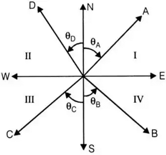
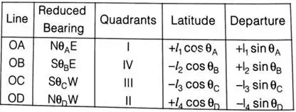
- Latitude and departure in various quadrants

Here, l1, l2, l3 and l4 are the length of line OA, OB, OC and OD respectively.
Independent Coordinate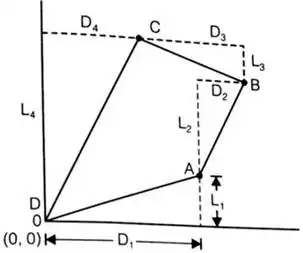 Closing Error
If sum of latitude, ∑L ≠ 0
and sum of departure ∑D ≠ 0
then there is a closing error
Closing error,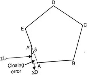
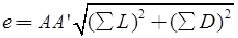
the direction of closing error (δ)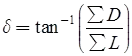
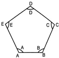
Adjustment of Closing Error
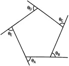
- Sum of all internal angles of a closed traverse = (2n - 4) × 90°
where n = no. of sides - Sum of all deflection angles = 360°
i.e. θA + θB + θC + θD + θE = 360° - Sum of latitude, ∑L = 0
sum of departure, ∑D = 0
Balancing the Traverse
- Bowditch method
Error in linear measurement ∝√l
Where l = length of a line
Error in angular measurement ∝1/√l
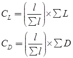
correction to a particular line
Here, l = length of a line,
CL = correction in latitude of a line
∑L = total error in latitude,
CD = correction in departure of a line
∑D = total error in departure
∑l = sum of length of all lines - Transit method
Correction in the latitude of all line,
CL = (L/LT) x ∑L
Correction in the departure of all line,
CD = (D/DT) x ∑D
Here, ∑L = Total error in latitude
∑D = total error in departure
L = latitude of a line
D = departure of a line
LT = sum of all latitude without considering sign
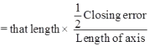
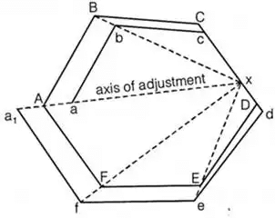
DT = Sum of all departure without considering sign. - Axis method
Correction to any length
i.e. Correction of

Triangulation
Definition: The horizontal control in Geodetic survey is established either by triangulation or by precise traverse. In triangulation, the system consists of a number of inter-connected triangles in which the length of only one line is called the base line and the angles of the triangle are measured very precisely.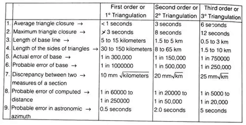
- Criterion of strength of figure
The strength of figure is a factor to be considered in establishing a triangulation system for which the computation can be maintained within a desired degree of precision.
The square of a probable error (L2) that would occur in the sixth place of the logarithm of any side,
L2 = (4/3)d2R
d = Probable error of an observed direction in seconds
D = Number of directions observed (forward and/or backward)
δA = Difference per second in the sixth place of a logarithms of the sine of the distance angle A of each triangle
δB = Same as δA but for the distance angle B
C = Number of angles and side conditions
C = (n’ – s’ + 1) + (n – 2s + 3)
n = Total number of lines
n’ = Number of lines observed in both directions
s = Total number of stations
s’ = Number of occupied stations
(n’ – s’ + 1) = Number of angle conditions
(n’ – 2δ + 3) = Number of side conditions

Signals and Towers
- A signal is a device erected to define the exact position of an observed station.
(i) Non Luminous Signals: Diameter of signal in cm = 1.3 D to 1.9 D Height of signal in cm = 13.3 D
where D = distance in km (Length of sight) for non-luminous signals
(ii) Luminous or Sun Signals: Used when the length of sight distance > 30 Km
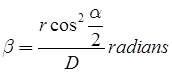
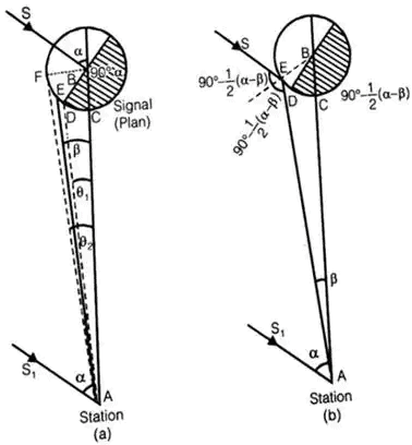
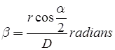
Phase of Signals: It is the error of bisection which arises, when the signal is partly in light and partly in shade. - Correction
(i) when observation is made on the bright portion.
Phase correction
α = Angle which the direction of sun makes with line of sight.
r = radius of the signal.
D = Distance of sight.
(ii) when the observation is made on the bright line:
Routine of Triangulation Survey
The routine of triangulation survey generally consists of the following operations:
- Reconnaissance
- Erection of singles and towers
- Measurement of base lines
- Measurement of horizontal angles
- Astronomical of horizontal angles
- Computations
Intervisibility and Height of Stations
- The distance between the stations: If here is no obstruction due to intervening ground, the distance of the visible horizon from a station of known elevation above datum is given by
where, h = height of the station above datum
D = distance to the visible horizon
R = mean radius of the earth - Relative elevation of stations: If there is no obstruction due to intervening ground, the formula may be used to get the necessary elevation of a station at distance, so that it may be visible from another station of known elevation Let, h1 = known elevation of station A above datum
h2 = required elevation of B above datum
D1 = distance from A to the point of tangency
D2 = distance from B to the point of tangency
D = the known distance between A and B
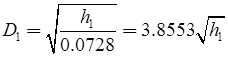
then, h1 = 0.6728D21
where D1 is in km and h1 is in meters, D2 = D – D1
h2 = 0.06728D22 meters - Profile of the intervening ground: In the reconnaissance, the elevations and positions of peaks in the intervening ground between the proposed stations should be determined. A comparison of their elevations should be made to the elevation of the proposed line of sight to ascertain whether the line of sight is clear off the obstruction or not. The problem can be solved by using the principles discussed in the factors (1) and (2) above, or by solutions suggested by Captain G.T. McCaw. The former method will be clear from the worked out examples.
 may be used to get the necessary elevation of a station at distance, so that it may be visible from another station of known elevation Let, h1 = known elevation of station A above datum
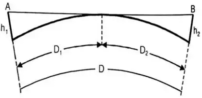
Captain GT McCaw’s Method
Let, h1 = height of station a above datum
h2 = height of station B above datum
h = height of line of sight at the obstruction C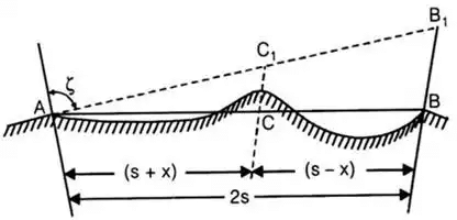
2s = distance between the two stations A and B
(s + x) = distance of obstruction C from A
(s – X) = distance of obstruction C from B
ζ = zenith distance from A to B
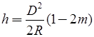
The height h of the line of sight at the obstruction is given by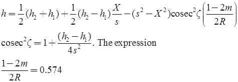
If X, s and R are substituted in miles, and h1, h2 and h are in feet.
and 1 - 2m/2R = 0.06728
If X, s and R are in km and h1, h2 and h are in meters.
|
19 videos|31 docs|35 tests
|
FAQs on Theodolite, Compass & Traverse Surveying - Geomatics Engineering (Surveying) - Civil Engineering (CE)
| 1. What is traverse surveying? |  |
| 2. How is a theodolite used in traverse surveying? | |
| 3. What is the role of a compass in traverse surveying? | |
| 4. What are the advantages of traverse surveying? | |
| 5. What are the limitations of traverse surveying? | |

|
4.93/5 Rating |

|
Dec 31, 2024 Last updated |

|
Explore Courses for Civil Engineering (CE) exam
|
|
ppt
,Theodolite
,shortcuts and tricks
,MCQs
,Objective type Questions
,mock tests for examination
,past year papers
,Viva Questions
,Compass & Traverse Surveying | Geomatics Engineering (Surveying) - Civil Engineering (CE)
,Free
,Previous Year Questions with Solutions
,video lectures
,Compass & Traverse Surveying | Geomatics Engineering (Surveying) - Civil Engineering (CE)
,Summary
,Important questions
,Extra Questions
,Compass & Traverse Surveying | Geomatics Engineering (Surveying) - Civil Engineering (CE)
,study material
,Sample Paper
,practice quizzes
,Theodolite
,Theodolite
,Semester Notes
,Exam
;


Theodolite, Compass & Traverse Surveying Free PDF Download
Importance of Theodolite, Compass & Traverse Surveying
Theodolite, Compass & Traverse Surveying Notes
Theodolite, Compass & Traverse Surveying Civil Engineering (CE) Questions
Study Theodolite, Compass & Traverse Surveying on the App
|
© EduRev
|
Education Revolution
|


|


