Lined & Unlined Canals | Irrigation Engineering - Civil Engineering (CE) PDF Download
Canal Design in General

Design Parameters
- The design considerations naturally change according to the type of soil.
- The velocity of the flow in the canal should be critical.
- Design methodologies of canals which are known as ‘Kennedy’s theory and ‘Lacey’s theory’ are based on the characteristics of sediment load (i.e. silt) in canal water.
Important Terms Related to Canal Design
- Alluvial soil: The soil which is formed by the continuous deposition of silt is known as the alluvial soil. The river has to carry a heavy charge of silt in the rainy season. When the river overflows its banks during flooding, the silt particles get deposited on the adjoining areas. This deposition of silt continues year after year. This type of soil is found in the deltaic region of a river. This soil is permeable, soft, and very fertile. The river passing through this type of soil has a tendency to frequently change its course.
- Non-alluvial soil: The soil which is formed by the disintegration of rock formations is termed non-alluvial soil. It is found in the initial mountainous region of a river. The soil is hard and impermeable in nature. This is not fertile. The river passing through this type of soil does not have a tendency to change its course.
- Silt factor: During his investigative work in various canals in alluvial soil, Gerald Lacey established the importance of the effect of silt on the determination of discharge and the canal section. He introduced a factor to account for this which is known as the ‘silt factor’. It depends on the mean size of the particle of silt. It is denoted by ‘f’. The silt factor is determined by the expression,
f = 1.76√dmm
where dmm id the mean particle size of silt in mm
- Co-efficient of rugosity: The roughness of the canal bed has an effect on the velocity of flow. This roughness is caused due to the ripples formed on the bed of the canal. So, a coefficient was introduced by R.G Kennedy to calculate the mean velocity of flow. This coefficient is known as the coefficient of rugosity and it is denoted by ‘n’. The value of ‘n’ depends on the type of material constituting the bed of the canal.
- Mean velocity: It is found by observations that the velocity at a depth of 0.6D from the surface represents the mean velocity (V), where ‘D’ is the depth of water in the canal or river.
 (i) Mean Velocity by Chezy's expression:
V = C√RS
(ii) Mean Velocity by Manning's expression:
V = (1/n)R2/3S1/2- Critical velocity: When the velocity of flow is such that there is no scouring or silting action in the canal bed, then that velocity is known as critical velocity. It is denoted by ‘Vo ’. Its value was given by Kennedy according to the following expression,
Vo = C.Dn
Where Vo = Critical velocity
D = Depth of channel
C & n = Constants
He found the values of C & n are 0.55 and 0.64
Therefore Vo = 0.55 × D0.64
Later he found that the critical velocity ratio has a huge impact on Critical velocity and he incorporated some changes in the above equation. - Critical velocity ratio (c.v.r), m: The ratio of mean velocity ‘V’ to the critical velocity ‘Vo ’ is known as the critical velocity ratio (CVR). It is denoted by m i.e.
CVR (m) = V/Vo
When m = 1, there will be no scouring or silting.
When m > 1, scouring will occur
When m < 1, silting will occur
So, by calculating the value of m, the condition of the canal can be predicted whether it will have scouring or silting. - Regime channel: When the character of the bed and bank materials of the channel is the same as that of the transported materials and when the silt grade and silt charge are constant, then the channel is said to be in its regime and the channel is called regime channel. This ideal condition is not practically possible.
- Hydraulic mean depth: It is the ratio of the cross-sectional area of flow to the wetted perimeter of the channel. It is generally denoted by R.
R = A / P
Where,
A = Cross-sectional area
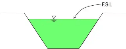
P = Wetted perimeter - Full supply discharge: Full supply discharge is the maximum capacity of the canal for which it is designed. The water level of the canal corresponding to the full supply of discharge is known as the full supply level (F.S.L).
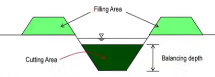
- Economical section: For the canal section such that the earth obtained from cutting (i.e. excavation) can be completely utilized in forming the banks, then that section is known as an economical section. Again, the discharge thus obtained will be maximum with minimum cross-section area. Here, no extra earth is required to be used from the borrow pit and no earth is in excess to form the spoil bank. This condition only arises in the case of partial cutting and partial banking. Sometimes, this condition is designated as the balancing of cutting and banking. Here, the cutting depth is called balancing depth.
Unlined Canal Design on Non-alluvial soil
The non-alluvial soils are stable and nearly impervious. For the design of a canal in this type of soil, the coefficient of rugosity has a very important role, but the other factors like the silt factor have no role. Here, the velocity of flow is considered to be very close to critical velocity. So, the mean velocity given by Chezy’s expression or Manning’s expression is considered for the design of the canal. The following formulae are adopted for the design.
- Mean velocity by Chezy's formula
V = C√RS
Where,
V = mean velocity in m/sec,
C = Chezy's constant,
R = hydraulic mean depth in m
S = bed slope of canal as 1 in n.
Again, the Chezy's constant C can be calculated by:
(i) Bazin's Formula:
(ii) Kutter's Formula:
- Mean velocity by Manning's formula
V = (1/n) R2/3S1/2 - Discharge by the following equations:
Q = A x V
Where,
Q = discharge in cumec
A = cross-sectional area of water section in m2
V = mean velocity in m/sec
Note:
- If the value of K is not provided, then it may be assumed as follows,
For unlined channel, K = 1.30 to 1.75.
For line channel, K = 0.45 to 0.85 - If the value of N is not provided, then it may be assumed as follows,
For unlined channel, N = 0.0225
For lined channel, N = 0.333
Example 1: Design an irrigation channel with the following data:
Discharge of the canal = 24 cumec
Permissible mean velocity = 0.80 m/sec.
Bed slope = 1 in 5000
Side slope = 1 : 1
Chezy's constant, C = 44
Solution: We know, A = 24 / 0.80 = 30m2
30 = (B + D)D
And P = B + 2.828D
But, R = 30 / (B + 2.828D)
From Chezy's formula, V = C√RS
⇒ 0.80 = 44 x 
∴ R = 1.65m
Putting the value of R and solving, D = 2.09m and b = 12.27m
Design of Unlined Canal on Alluvial soil by Kennedy’s Theory
R.G Kennedy established a theory which states that the silt carried by flowing water in a channel is kept in suspension by the vertical component of eddy currents which are formed over the entire bed width of the channel and the suspended silt rises up gently towards the surface.
His theory makes the following assumptions:
- The eddy currents are developed due to the roughness of the bed.
- The quantity of the suspended silt in the stream is proportional to bed width.
- This theory is applicable to those channels which are flowing through the bed consisting of sandy silt or same grade of silt.
He established the idea of a critical velocity ‘Vo ’ that will make the channel free from silting or scouring. From long observations, he established a relationship between the critical velocity and full supply depth as follows,
Vo = C Dn
The values of C and n were found to be 0.546 and 0.64 respectively, thus
Vo = 0.546 D0.64
He also observed that the critical velocity was affected by the grade of silt and introduced another factor (m) which is known as the critical velocity ratio (C.V.R).
Vo = 0.546 m D0.64
Drawbacks of Kennedy’s Theory
- The theory is limited to the average regime channel only.
- The design of the channel is based on the trial and error method.
- The value of m was fixed arbitrarily.
- Silt charge and silt grade are not considered.
- There is no equation to determine the bed slope and it depends on Kutter’s equation only.
- The ratio of ‘B’ to ‘D’ has no significance in his theory.
Design Procedure
- Critical velocity, Vo =0.546 m D0.64 .
- Mean velocity, V = C (RS)1/2
Where,
m = critical velocity ratio,
D = full supply depth in m,
R = hydraulic mean depth of radius in m,
S = bed slope as 1 in ‘n’.
The value of ‘C’ is calculated as per Kutter’s formula
Where,
n = rugosity coefficient which is taken as an unlined earthen channel. - The B/D ratio is assumed between 3.5 to 12.
- Discharge, Q = A*V
Where,
A = Cross-section area in m2 ,
V = mean velocity in m/sec - The full supply depth is determined by trial to satisfy the value of ‘m’. Generally, a trial depth between 1 m to 2 m is assumed. If the conditions are not satisfied within these limits, then a different value may be assumed accordingly.
Example 2: Design an irrigation channel with the following data:
Full supply discharge = 6 cumec
Rugosity coefficient(n) = 0.0225
C.V.R(m) = 1
Bed slope = 1 in 5000
Assume other reasonable data for the design
Solution:
First Trial:
Assume, Full supply depth, D = 1 / .5m
Critical velocity, V0 = 0.546 x 1 x 1.50.64 = 0.707 [Assume, m = 1]
As m = 1, V = V0
∴ A = 6 / 0.707 = 8.49m
A = (2B + 3) / 2 x 1.5 = 1.5B + 2.25 ⇒ B = 4.16m
P = B + 2√2 x 1.5 = B + 4.24 = 8.40m
R = 416 / 8.40 = 1.0m
By Kutter's formula, C = 
By Chezy's formula, V = 44.49 x √1 x 0.0002) = 0.629 m/sec
C.V.R = 0.629 / 0.707 = 0.889 < 1
As the C.V.R is much less than 1, the channel will be in silting. So, the design is not satisfactory. Here, the full supply depth is to be assumed by trials to get thhe satisfactory result.
Second Trial:
Assume, Full supply depth, D = 1.25m
Critical velocity, V0 = 0.546 x 1 x 1.250.64 = 0.629[Assume, m = 1]
As m = 1, V = V0
∴ A = 6 / 0.629 = 9.53m
A = 1.25B + 1.56 ⇒ B = 6.38
P = B + 2√2 x 1.25 = 9.92m
R = 0.96m
By kutter's formula, 
By Chezy's formula, V = 44.23 x √(1 x 0.0002) = 0.613m/sec
C.V.R = 0.613 / 0.629 = 0.97 < 1
In this case, the CVR is very close to 1. So, the design may be accepted. So, finally,
D = 1.25 m and B = 6.28m
Try Yourself
Problem-1
Find the maximum discharge through an irrigation channel having the bed width 4m and fully supply depth is 1.50m. Given that n = 0.02,
S = 0.0002, side slope = 1 : 1
Assume reasonable data, if necessary. Comment whether the channel will be in scouring or silting.
Problem-2
Design an irrigation channel with the following data:
Full supply discharge = 10cumec
Bazin's constant, k = 1.3
C.V.R(m) = 1
B/D ratio = 4
Side slope = 1 : 1
Assume other reasonable data for the design
Design of Unlined Canals in Alluvial soil by Lacey’s Theory
Lacey’s theory is based on the concept of the regime condition of a channel which will be satisfied if,
- The channel is flowing uniformly in unlimited incoherent alluvium of the same character which is being transported by the channel.
- The silt grade and silt charge remain constant.
- The discharge remains constant.
Lacey observed that the silt carried by the flowing water is kept in suspension by the vertical component of eddies. These eddies are generated at all the points on the wetted perimeter of the channel section. Again, he assumed the hydraulic mean radius (R) as the variable factor and he recognized the importance of silt grade and he introduced a factor to account for it which is known as silt factor ‘f’.
Thus, he deduced the velocity as;
V = (2/5f R)0.5
Where,
V = mean velocity in m/sec,
f = silt factor,
R = hydraulic mean radius in meter
Then he derived the relationship between A, V, Q, P, S and f are as follows:
- f = 1.76 x √dmm
- Af2 = 140 x V5
- V =

- P = 4.75 x √Q
- Regime flow equation, V = 10.8 x R2/3 x S1/3
- Regime scour depth
R = 135(q2/f)1/3
Bed slope, S = f5/3/3340Q1/6
Example 3: Design an irrigation channel with the following data:
Full supply discharge = 10 cumec
Mean diameter of silt particles = 0.33mm
Side slope = 1 / 2 : 1
Find also the bed slope of the channel
Solution: f = 1.76 x √0.33 = 1.0 and V = 
A = 10 / 0.64 = 16.62m2
P = 4.75 x √10 = 15.02m
R = 0.47 x (10 / 1)1/3 = 1.02m
S = 
But, A = BD + 0.5D2
⇒ 15.62 = BD + 0.5D2 .....(i)
P = B + √5D
15.02 = B + 2.24D .....(ii)
Solving equation (i) & (ii) D = 1.21m and B = 12.30m
Drawbacks of Lacey’s Theory
- The concept of the true regime is a theoretical one and can not be achieved practically.
- The various equations are derived by considering the silt factor f to be a constant which is not at all constant.
- The concentration of silt is not considered.
- Silt grade and silt charge is not taken into account.
- The equations are empirical and based on the available data from a particular type of channel and may not hold true for a different type of channel.
- The characteristics of the regime channel may not be the same for different cases.
Comparison between Kennedy’s and Lacey’s theory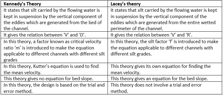
Design of Lined Canal
- The section should be economical (i.e. cross-sectional area should be maximum with a minimum wetted perimeter).
- The velocity should be maximum so that the cross-sectional area can be minimized.
- Silting does not reduce the capacity of the lined section.
Section of Lined Canal
The following two-lined sections are generally adopted:
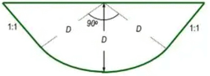
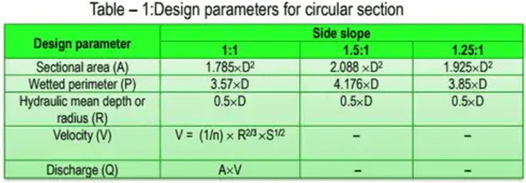
- Circular section: The bed is circular with a radius equal to full supply depth ‘D’ and its centre at the full supply level. The sides are tangential to the curve. However, the side slopes are generally taken to be 1 : 1.
- Trapezoidal section: The horizontal bed is connected to the side slope by a curve of radius equal to full supply depth D. The side slope is generally kept as 1 : 1.
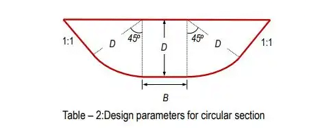

Note: For the discharge of up to 50 cumecs, a circular section is suitable and for the higher discharges trapezoidal section is suitable.
Example 4: Design a lined canal having the following data:
Full supply discharge = 200 cumec
Side slope = 1.25 : 1
Bed slope = 1 in 5000
Rugosity coefficient = 0.018
Permissible velocity = 1.75 cumec
Solution: Since the discharge is more than 50 cumec, the trapezoidal section will be acceptable.
From table-2,
Sectional area, A = BD + 1.925D2 ...(i)
Wetted perimeter, P = B + 3.85 D ...(ii)
Now, A = 200 / 1.75 = 114.28m2
Again, V = (1 / n) x R2/3xS1/2
⇒ 1.75 = (1 / 0.018) x R2/3x (0.0002)1/2
∴ R = 3.32m
P = 114.28 / 3.32 = 34.42m
From equation(i) ⇒ 114.28 = BD + 1.925 x D2
From equation(ii) ⇒ 34.42 = B + 3.85 x D
Solving equation (i) &(ii) ⇒ D = 4.4m(full supply depth)
∴ B = 17.5m (Bed width)
|
7 videos|47 docs|31 tests
|
FAQs on Lined & Unlined Canals - Irrigation Engineering - Civil Engineering (CE)
| 1. What is the purpose of lining canals in civil engineering? |  |
| 2. What materials are commonly used for lining canals? |  |
| 3. What are the advantages of lining canals? |  |
| 4. What are the disadvantages of lining canals? |  |
| 5. What are unlined canals and when are they preferred over lined canals? |  |


