Mechanical Engineering Exam > Mechanical Engineering Notes > Manufacturing Engineering > Geometric Modeling
Geometric Modeling | Manufacturing Engineering - Mechanical Engineering PDF Download

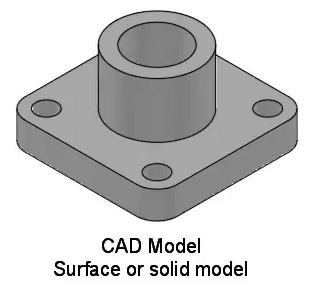
Solid Modeling
Also known as volume modeling, this is the most widely used method as it provides a complete description of solid modeling. Solid modeling defines an object by its nodes, edges, and surfaces; therefore, it gives a perfect and explicit mathematical representation of a precisely enclosed and filled volume. Solid modeling requires the use of topology rules to guarantee that all surfaces are stitched together correctly. This geometry modeling procedure is based upon the “Half-Space” concept.
There are two prevalent ways for representing solid models:
- Constructive solid geometry: Constructive solid geometry is a combination of primary solid objects (prism, cylinder, cone, sphere, etc.). These shapes are either added or deleted to form the final solid shape.
- Boundary representation: In boundary representation, an object’s definition is determined by their spatial boundaries. It describes the points, edges, surfaces of a volume, and issues command to rotate, sweep a binds facets into a third dimensional solid. The union of these surfaces enables the formation of a surface that explicitly encloses a volume.
Solid Modeling is the most widely used geometric modeling in three dimensions, and it serves the following purpose:
- Solid modeling supports weight or volume calculation, centroids, moments of inertia calculation, stress analysis, heat conduction calculations, dynamic analysis, system dynamics analysis.
- Solid modeling supports the generation of codes, robotic and assembly simulation
- Solid modeling stores both geometric and topological information; can verify if the two objects occupy same space
- Solid modeling improves the quality of design, enhances visualization, and has the potential for functional automation and integration.
Different solid modeling techniques are as follows:
- Constructive Solid Geometry
- Boundary Representation
- Feature-based modeling
- Primitive Instancing
- Cell decomposition, spatial enumeration, octree
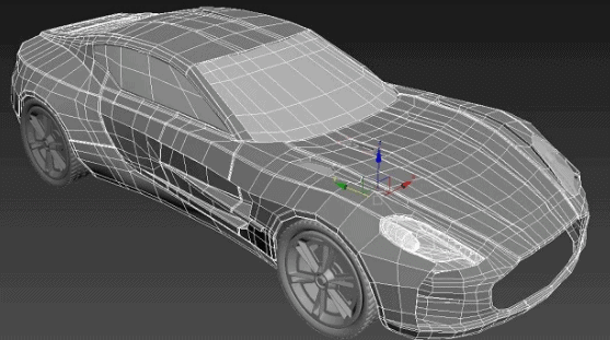
Surface Modeling
Surface modeling represents the solid appearing object. Although it is a complicated method of representation than wireframe modeling, it is not as refined as solid modeling. Although surface models and solid models look identical, the former cannot be sliced open the way solid models can be. This model makes use of B-splines and Bezier for controlling curves.
A typical surface modeling process involves the following steps:
- Generation of a model combining the three-dimensional surfaces and solids
- Conversion of the model to surfaces, taking advantage of associative modeling
- Validation of imperfections with surface analysis tools
- Reconstructing surfaces of objects to apply smoothness to the object
Surface modeling is used to:
- To shape design and representation of complicated objects such as a car, ship, and airplane bodies as well as castings
- There are situations where models imported from another CAD system usually lack details of the features it is comprised of. If the surfaces are complex, applying changes to this type of geometry can be quite the task. In such cases, surface modeling techniques can be used to one or more faces of the model to make the desired changes.
- Surface modeling enables building one face at a time so that one can control the exact contour and direction of any face. This feature comes in handy at a time when solid modeling technique fails to create the complex shape of a feature as it builds up several sides of shape at once.
- As it is not limited to the direct construction of a model face, surfaces can also be used as a reference geometry in a transitional step towards the creation of the required model face.
- Now, there is another modeling technique which requires a combination of solid and surface modeling techniques to create a solid model. This technique generally involves starting the model as a solid and using surfaces to modify it. Or, changing the solid to surfaces to shape and contour it, then turning it back to a solid when done.
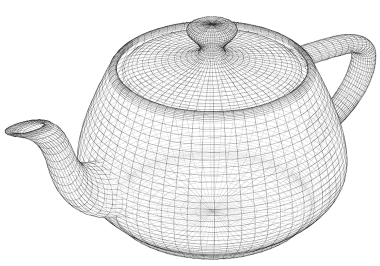
Wireframe Modeling
- The wireframe model is perhaps one of the earliest ways of representing a solid model. It consists of vertices and lines and is a skeletal representation of a real-world 3D object. It was developed back in the 1960s; it is also referred to as “Stick figure” or “edge representation.”

- The lines within a wireframe connect to create polygons, such as triangles and rectangles, that represent three-dimensional shapes when bound together. The outcome may range from a cube to a complex three-dimensional scene with people and objects. The number of polygons within a model is a good indicator of how detailed the wireframe 3D model is.
- Wireframe modeling helps in matching a 3D drawing model to its reference. It allows the creator to match the vertex points, so they are in alignment with the desired reference and see the reference through the model as well. Although Wireframe modeling is a quick and easy way to demonstrate concepts, creating a fully detailed, precisely constructed model for an idea can be extremely time-consuming, and if it does not match what was visualized for the project, all that time and effort was wasted. In wireframe modeling, one can skip the detailed work and present a very skeletal framework that is simple to create and is apprehensible to others.
The document Geometric Modeling | Manufacturing Engineering - Mechanical Engineering is a part of the Mechanical Engineering Course Manufacturing Engineering.
All you need of Mechanical Engineering at this link: Mechanical Engineering
|
52 videos|54 docs|29 tests
|
Related Exams
About this Document

4.63/5
Rating

Feb 19, 2025
Last updated
Document Description: Geometric Modeling for Mechanical Engineering 2025 is part of Manufacturing Engineering preparation.
The notes and questions for Geometric Modeling have been prepared according to the Mechanical Engineering exam syllabus. Information about Geometric Modeling covers topics
like and Geometric Modeling Example, for Mechanical Engineering 2025 Exam. Find important definitions, questions, notes, meanings, examples, exercises and tests below for Geometric Modeling.
Introduction of Geometric Modeling in English is available as part of our Manufacturing Engineering
for Mechanical Engineering & Geometric Modeling in Hindi for Manufacturing Engineering course.
Download more important topics related with notes, lectures and mock test series for Mechanical Engineering
Exam by signing up for free. Mechanical Engineering: Geometric Modeling | Manufacturing Engineering - Mechanical Engineering
Description
Full syllabus notes, lecture & questions for Geometric Modeling | Manufacturing Engineering - Mechanical Engineering - Mechanical Engineering | Plus excerises question with solution to help you revise complete syllabus for Manufacturing Engineering | Best notes, free PDF download
Information about Geometric Modeling
In this doc you can find the meaning of Geometric Modeling defined & explained in the simplest way possible. Besides explaining types of
Geometric Modeling theory, EduRev gives you an ample number of questions to practice Geometric Modeling tests, examples and also practice Mechanical Engineering
tests

Related Searches
Sample Paper
,Extra Questions
,study material
,Geometric Modeling | Manufacturing Engineering - Mechanical Engineering
,Previous Year Questions with Solutions
,ppt
,MCQs
,Free
,mock tests for examination
,video lectures
,Geometric Modeling | Manufacturing Engineering - Mechanical Engineering
,Viva Questions
,Geometric Modeling | Manufacturing Engineering - Mechanical Engineering
,practice quizzes
,Summary
,Semester Notes
,shortcuts and tricks
,Exam
,past year papers
,Important questions
,Objective type Questions
,


Additional Information about Geometric Modeling for Mechanical Engineering Preparation
Geometric Modeling Free PDF Download
The Geometric Modeling is an invaluable resource that delves deep into the core of the Mechanical Engineering exam.
These study notes are curated by experts and cover all the essential topics and concepts, making your preparation more efficient and effective.
With the help of these notes, you can grasp complex subjects quickly, revise important points easily,
and reinforce your understanding of key concepts. The study notes are presented in a concise and easy-to-understand manner,
allowing you to optimize your learning process. Whether you're looking for best-recommended books, sample papers, study material,
or toppers' notes, this PDF has got you covered. Download the Geometric Modeling now and kickstart your journey towards success in the Mechanical Engineering exam.
Importance of Geometric Modeling
The importance of Geometric Modeling cannot be overstated, especially for Mechanical Engineering aspirants.
This document holds the key to success in the Mechanical Engineering exam.
It offers a detailed understanding of the concept, providing invaluable insights into the topic.
By knowing the concepts well in advance, students can plan their preparation effectively.
Utilize this indispensable guide for a well-rounded preparation and achieve your desired results.
Geometric Modeling Notes
Geometric Modeling Notes offer in-depth insights into the specific topic to help you master it with ease.
This comprehensive document covers all aspects related to Geometric Modeling.
It includes detailed information about the exam syllabus, recommended books, and study materials for a well-rounded preparation.
Practice papers and question papers enable you to assess your progress effectively.
Additionally, the paper analysis provides valuable tips for tackling the exam strategically.
Access to Toppers' notes gives you an edge in understanding complex concepts.
Whether you're a beginner or aiming for advanced proficiency, Geometric Modeling Notes on EduRev are your ultimate resource for success.
Geometric Modeling Mechanical Engineering Questions
The "Geometric Modeling Mechanical Engineering Questions" guide is a valuable resource for all aspiring students preparing for the
Mechanical Engineering exam. It focuses on providing a wide range of practice questions to help students gauge
their understanding of the exam topics. These questions cover the entire syllabus, ensuring comprehensive preparation.
The guide includes previous years' question papers for students to familiarize themselves with the exam's format and difficulty level.
Additionally, it offers subject-specific question banks, allowing students to focus on weak areas and improve their performance.
Study Geometric Modeling on the App
Students of Mechanical Engineering can study Geometric Modeling alongwith tests & analysis from the EduRev app,
which will help them while preparing for their exam. Apart from the Geometric Modeling,
students can also utilize the EduRev App for other study materials such as previous year question papers, syllabus, important questions, etc.
The EduRev App will make your learning easier as you can access it from anywhere you want.
The content of Geometric Modeling is prepared as per the latest Mechanical Engineering syllabus.
|
© EduRev
|
Education Revolution
|


|


Signup to see your scores
go up within 7 days!
Access 1000+ FREE Docs, Videos and Tests
Takes less than 10 seconds to signup