Diode as a Rectifier | Physics Class 12 - NEET PDF Download

Application of junction diode as a Rectifier
- Rectifier is a device which is used for converting alternating current or voltage into direct current or voltage
- A p-n junction diode can be used as a half-wave and full-wave rectifier
- The resistance of a p-n junction diode becomes low when forward biased and becomes high when reverse biased. This is the principle of the working of rectifier
Half-wave Rectifier
Circuit Diagram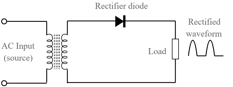
- Transformer with primary and secondary coils
- Diode
- Load resistance RL
The AC voltage to be rectified is connected between the primary of the transformer
To one coil of the secondary, the p junction of the diode is connected
The output is measured across the load resistance RL
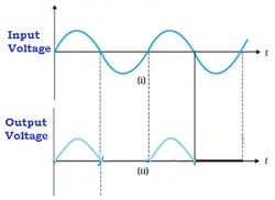
Input and output
Working
➤ Case 1
- During the positive half cycle of the input AC voltage, suppose P1 is negative and P2 is positive
- On account of inductance, S1 becomes positive and S2 becomes negative
- The p-n junction is forward biased and hence the resistance of the p-n junction diode becomes low
- Hence, current flows in the circuit and we get output across the load resistance RL
- This is indicated in the graph above
➤ Case 2
- During the negative half cycle of the input AC voltage, suppose P1 is positive and P2 is negative
- On account of inductance, S1 becomes negative and S2 becomes positive
- The p-n junction is reverse biased and hence the resistance of the p-n junction diode becomes high
- Hence, no current flows in the circuit and we do not get any output across the load resistance RL
- This is indicated in the graph above
The above process is repeated. Thus , we have current only in the positive half of the cycle. Hence, if is called as half-wave rectifier
The output signal is not continuous and available as bursts. Hence, this is not of much use.
Full Wave Rectifier
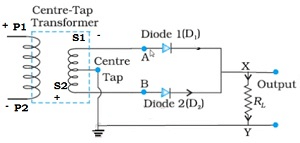
➤ Circuit Diagram
- The main difference between half and full wave rectifier in circuit, is the usage of two diodes – D1 and D2
➤ Input and Output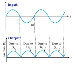
Working
➤ Case 1
- During the positive half of the input cycle of AC voltage, the junction diode D1 is forward biased as shown in the diagram above
- Hence, current flows in the above circuit as indicated
- The diode D2 is reverse biased and hence no current due to D2
- We get output when the same is measured across the load resistance RL due to the diode D1 alone
➤ Case 2
- The circuit diagram for the negative half of the input cycle of AC voltage:
- During the positive half of the input cycle of AC voltage, the junction diode D2 is forward biased as shown in the diagram above.
- Hence, current flows in the above circuit as indicated.
- The diode D1 is reverse biased and hence no current due to D1.
- We get output when the same is measured across the load resistance RL due to the diode D2 alone
We observe that one of the diode conducts and the flow of current across the load resistance is in the same direction Also, current flows during both cycles of the input AC voltage. However, the output though unidirectional has ripple contents. Ripple contents indicate both AC and DC components
We can get only the DC component by passing it through a filter circuit
The filter circuit consists of Resistance and Capacitance
➤ Circuit Diagram
- C has a high capacitance value and serves as a filter circuit
- RL is a load resistance
➤ Working
- The capacitance offers low impedance to AC component and offers infinite impedance to DC component
- Due to this the AC component is bypassed or filtered out
- The DC component produces a voltage drop across the load resistance which is almost DC voltage
Problem: In half-wave rectification, what is the output frequency if the input frequency is 50 Hz. What is the output frequency of full wave rectifier for the same input frequency?
Solution: Half-wave rectifier –The output voltage is obtained is once in one cycle of input voltage, hence output ripple frequency after half-wave rectification = 50 Hz
Full-wave rectifier – For one cycle of input voltage, we get output twice in the same direction. Hence, the output after full wave rectification = 100 Hz
|
74 videos|314 docs|88 tests
|
FAQs on Diode as a Rectifier - Physics Class 12 - NEET
| 1. What is a rectifier? |  |
| 2. How does a junction diode function as a rectifier? | |
| 3. What is the difference between a half-wave rectifier and a full-wave rectifier? | |
| 4. What are the advantages of using a full-wave rectifier over a half-wave rectifier? | |
| 5. Can a junction diode be used as a rectifier in high-power applications? | |


Diode as a Rectifier | Physics Class 12 - NEET
,practice quizzes
,Extra Questions
,study material
,Objective type Questions
,Free
,video lectures
,past year papers
,MCQs
,Exam
,Diode as a Rectifier | Physics Class 12 - NEET
,Sample Paper
,Diode as a Rectifier | Physics Class 12 - NEET
,Previous Year Questions with Solutions
,shortcuts and tricks
,Semester Notes
,Important questions
,Viva Questions
,Summary
,ppt
,mock tests for examination
;


Diode as a Rectifier Free PDF Download
Importance of Diode as a Rectifier
Diode as a Rectifier Notes
Diode as a Rectifier NEET Questions
Study Diode as a Rectifier on the App
|
© EduRev
|
Education Revolution
|


|


