Rigid Pavement | Transportation Engineering - Civil Engineering (CE) PDF Download
Introduction
Rigid pavements are those which posses note worthy flexural strength or flexural rigidity. The stresses are not transferred from grain to grain to the lower layers as in the ease of flexible pavement layers. The rigid pavements are made of Portland cement concrete-either plain, reinforced or prestressed concrete. The plain cement concrete slabs are expected to take-up about 40 kg/cm2 flexural stress.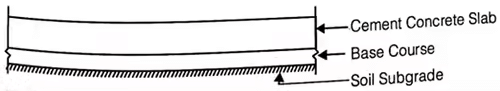
(i) Modulus of subgrade reaction (k),
k = P/Δ
where, k = Modulus of subgrade reaction (kg/cm2/cm)
p = Pressure required for ‘Δ’ deflection (kg/cm2)
Δ = Deflection(cm)
For 75 cm dia plate, Δ = 1.25 mm
(ii) Radius of Relative Stiffness (l)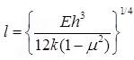
where, l = Radius of relative stiffness, cm
E = Modulus of elasticity of cement concrete (kg/cm2)
μ = Poisson’s ratio for concrete = 0.15
h = Slap thickness (cm)
k = Subgrade modulus or modulus of subgrade reaction (kg/cm3)
(iii) Equivalent Radius of Resisting Section (b)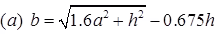
when a < 1.724 h
(b) b = a when a > 1.724h
where, a = Radius of contact area (cm)
h = Slab thickness (cm)
(iv) Glodbeck’s Formula for Stress due to Corner Load
SC = 3P/h2
where, SC = Stress due to corner load (kg/cm2)
P = Corner load assumed as a concentrated point load, (kg)
h = Thickness of slab (cm).
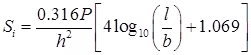
(v) Westergards Stress Equation
(a) Stress at Interior Loading (Si)
(b) Stress at Edge Loading (Se)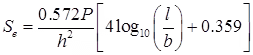
(c) Stress at Corner Loading (Sc)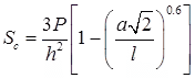
where, h = Slab thickness (cm)
P = Wheel load (kg)
a = Radius of contact area (cm)
l = Radius of relative stiffness (cm)
b = Radius at resisting section (cm).
(vi) Warping Stresses
(a) Stress at Interior Region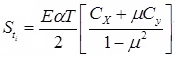
where, Warping stress at interior region (kg/cm2)
E = Modulus of elasticity of concrete, (kg/cm2)
α = Coefficient of thermal expansion (/°c)
CX = Coefficient based on (Lx/l) in desired direction.
Cy = Coefficient based on (Ly/l) in right angle to the above direction.
μ = Poissons’s ratio ∼ 0.15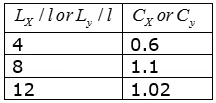
LX & Ly are the dimensions of the slab considering along X & y directions along the length & width of slab.
(b) Stress at Edge Region
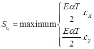
(c) Stress Corner Region
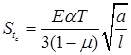
where, a = Radius of contact area
l = Radius of relative stiffness
(vii) Frictional Stress (Sf)
where, SF = Frictional stress (kg/cm2)
W = Unit weight of concrete, (kg/cm3)
f = Friction constant or coefficient of subgrade restraint
L = Slab length (m)
B = Slab width (m)
(viii) Combination of Stresses
- Critical Combination During Summer
(a) Stress for edge/interior regions at Bottom = (+ load stress) + (warping stress of day time) – Frictional stress
(b) Stress for corner region at top = (+ load stress + warping stress at night) - Critical Combination During Winter
(a) Stress for edge/interior at bottom = (+ load stress + warping stress at day time + Frictional stress)
(b) Stress for corner at top = (load stress + warping stress at night)
Design of Joints in Cement Concrete Pavements
(i) The spacing of expansion joints, (Le)
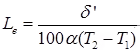
Where, δ’ = Maximum expansion in slab (cm)
Le = Spacing of expansion joint (m)
α = Coefficient of thermal expansion of concrete (/°c)
(ii) The spacing of the contraction joint, (Lc)
(a) When reinforcement is not provided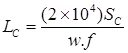
where, Lc = Spacing of contraction joint (m)
SC = Allowable stress in tension in cement concrete.
f = Coefficient friction ∼ 1.5
w = Unit weight of cement concrete (kg/m3).
(b) When reinforcement is provided
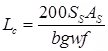
where, SS = Allowable tensile stress in steel (kg/cm2)
∼ 1400kg/cm2
AS = Total area of steel in cm2.
(iii) Longitudinal Joints
(a) 
where, AS = Area of steel required per meter length of joint (cm2)
b = Distance between the joint & nearest free edge (m)
h = Thickness of the pavement (cm)
f = Coeff. of friction ∼ 1.5
w = Unit wt. of concrete (kg/cm3)
Ss = Allowable working stress in tension for steel (kg/cm2)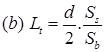
where, Lt = Length of tie bar
SS = Allowable stress in tension (kg/cm2) ∼ 1400
Sb = Allowable bond stress in concrete (kg/cm2)
= 24.6 kg/cm2 for deformed bars
= 17.5 kg/cm2 for plain tie bars
d = diameter of tie bar (cm).
IRC Recommendations for Design of Cement Concrete Pavements
Ad = P’[1 + r](n + 20)
where, Ad = Number of commercial vehicles per day (laden weight > 3 tonnes)
P’ = Number of commercial vehicles per day at last count.
r = Annual rate of increase in traffic intensity.
n = Number of years between the last traffic count & the commissioning of new cement concrete pavement.
|
26 videos|91 docs|58 tests
|

|
4.60/5 Rating |

|
Dec 22, 2024 Last updated |

|
Explore Courses for Civil Engineering (CE) exam
|
|
Sample Paper
,mock tests for examination
,Free
,ppt
,practice quizzes
,Important questions
,Exam
,Viva Questions
,Semester Notes
,video lectures
,Rigid Pavement | Transportation Engineering - Civil Engineering (CE)
,Rigid Pavement | Transportation Engineering - Civil Engineering (CE)
,Summary
,Rigid Pavement | Transportation Engineering - Civil Engineering (CE)
,Extra Questions
,past year papers
,shortcuts and tricks
,MCQs
,study material
,Previous Year Questions with Solutions
,Objective type Questions
,


Rigid Pavement Free PDF Download
Importance of Rigid Pavement
Rigid Pavement Notes
Rigid Pavement Civil Engineering (CE) Questions
Study Rigid Pavement on the App
|
© EduRev
|
Education Revolution
|


|


