Turbomachinery- Notes


Introduction
A turbomachine is a mechanical device in which energy is transferred between a flowing fluid and a rotating element, producing a change in the fluid's pressure and momentum. The energy exchange is transmitted mechanically via input or output shafts. Turbomachines are widely used for power generation, propulsion and fluid transport.
Principal parts of a turbomachine
- Rotating element (the rotor) on which blades or buckets are mounted.
- Stationary element (the stator) in the form of guide blades, nozzles or diffusers.
- Input or output shaft that transmits mechanical power.
- Housing (casing) that protects components and provides a flow path for the fluid.
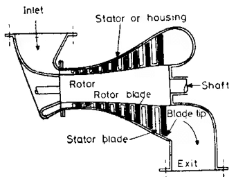
A schematic cross-sectional view of a steam turbine showing the principal parts of a turbomachine.
Functions of each part
- The rotor absorbs or delivers mechanical energy to the flowing fluid by exchanging momentum with it.
- The stator is a stationary assembly whose common forms and functions are:
- Guide blades: direct the approaching fluid to optimise the relative velocity and incidence on rotor blades.
- Nozzles: convert fluid pressure (or enthalpy) into kinetic energy (high velocity jets).
- Diffusers: convert kinetic energy back into pressure energy where required.
- The shaft transmits mechanical energy to or from the rotor to the external machine (prime mover or driven equipment).
- The housing encloses the machine, supports bearings and seals, and provides the fluid path. Note: rotor and shaft are essential; stator and housing may be configured according to machine type and are sometimes minimal in simple designs.
Classification of turbomachines
Turbomachines are classified in several ways depending on the direction of energy transfer, flow geometry, and head/discharge characteristics.
Classification by the nature of energy transfer
- Power generating turbomachines: Energy is transferred from the fluid to the rotor; the fluid enthalpy decreases while mechanical work appears at the output shaft.
- Examples: Hydraulic turbines (Pelton wheel, Francis turbine, Kaplan turbine), steam turbines (De Laval, Parsons), gas turbines.
- Power absorbing turbomachines: Energy is transferred from the rotor to the fluid; the fluid enthalpy increases and the machine requires input shaft power.
- Examples: Centrifugal pump, compressors, blowers, fans.
- Power transmitting turbomachines: Energy is transferred from one rotor to another using a fluid coupling between them; both input and output shafts are present.
- Examples: Hydraulic couplings, torque converters.
Classification by fluid flow direction
- Tangential flow: Fluid flows tangentially to the rotor circumference.
- Example: Pelton wheel.
- Axial flow: Fluid flows approximately parallel to the shaft axis.
- Examples: Kaplan turbine, axial-flow compressors, axial fans.
- Radial flow: Fluid flows along the radius of the rotor.
- Radially inward flow: example - some impulse turbines.
- Radially outward flow: example - centrifugal pumps and many centrifugal compressors.
- Mixed flow: Flow has both radial and axial components (radial entry with axial exit or vice versa).
- Examples: Modern Francis turbines, some mixed-flow pumps.
Classification by type of head (hydraulic turbines)
- High head, low discharge: Example - Pelton wheel.
- Medium head, medium discharge: Example - Francis turbine.
- Low head, high discharge: Example - Kaplan turbine.
Application of the first and second laws of thermodynamics to turbomachines
Because properties in a turbomachine are often steady over time at each section, turbomachines are treated as steady-flow devices and analysed using the steady flow energy equation (SFEE). Thermal losses in many turbomachines are small relative to the mechanical energy exchanged and may be neglected in a first approximation.
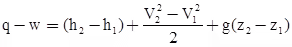
Here the subscripts 1 and 2 indicate inlet and outlet conditions respectively.
Using stagnation (total) enthalpy notation, the shaft work per unit mass exchanged by the machine can be written as the change in stagnation enthalpy:
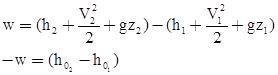
Where h01 and h02 are stagnation (total) enthalpies at inlet and outlet respectively, and w denotes specific work exchanged. Thus w = Δh0.
Sign conventions:
- In a power generating turbomachine Δh0 is negative (h02 < h01), so w is positive (work delivered).
- In a power absorbing turbomachine Δh0 is positive (h02 > h01), so w is negative (work absorbed).
From the second law of thermodynamics, irreversibilities reduce the available work. In differential form:
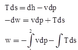
In this relation, the v dp term reflects work associated with pressure-volume interactions and its sign depends on whether the machine is generating or absorbing power (negative for power generating machines and positive for power absorbing machines). The T ds term is always positive for irreversible processes and reduces the useful work obtainable from the flow (it reduces generated work; it increases work absorbed when considering input shaft power required).
Efficiency of a turbomachine
To account for losses, two main efficiencies are defined for turbomachines:
- Hydraulic (or isentropic) efficiency - accounts for losses between the fluid and the rotor due to fluid friction, flow separation and irreversibility in expansion/compression.
- Mechanical efficiency - accounts for losses between the rotor and the shaft (bearing friction, seal losses, gear losses etc.).
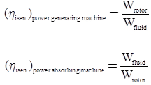
Hydraulic (isentropic) efficiency
Hydraulic efficiency compares the actual work exchanged with the ideal (isentropic) work for the same inlet and outlet pressures (or enthalpies). It is defined to measure how closely the machine approaches an isentropic process between designated states.
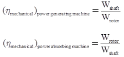
Mechanical efficiency
Mechanical efficiency accounts for losses occurring on the shaft due to bearings and rotating element friction. The power available at the shaft equals the aerodynamic/hydraulic power minus mechanical losses.
Schematic representation of compression and expansion processes
- Power absorbing machine (compression process: fluid enthalpy increases).
- Power generating machine (expansion process: fluid enthalpy decreases).
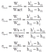
- Power generating machine
Actual specific work: Wact = h01 - h02
Isentropic (ideal) specific work: Wisen = h01 - h102
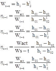
- Power absorbing turbomachine
Actual specific work: Wact = h02 - h01
Isentropic (ideal) specific work: Wisen = h102 - h01
Analysis of energy transfer in turbomachines
The energy transfer analysis requires consideration of kinematics and dynamics of the fluid relative to moving blades. The primary factors are changes in fluid velocity (vector), blade tangential speed, and the forces due to changes in momentum.
Applying Newton's second law for rotational motion leads to the relation between torque and the rate of change of angular momentum:
T = d(m·Vθ·r)/dt
where Vθ is the tangential (circumferential) component of fluid velocity and r is the radius at which the fluid interacts with the blades. For steady flow of mass rate ṁ, the torque exerted on the rotor is
T = ṁ·(r·Vθ1 - r·Vθ2)
The power exchanged at the shaft is then P = T·ω = ṁ·U·(Vθ1 - Vθ2), where U = ω·r is the blade peripheral speed. Per unit mass, the Euler turbine equation (specific work) is commonly written as
w = U·(Vθ1 - Vθ2)
This expression emphasises that the tangential components of velocity at inlet and outlet (Vθ1, Vθ2) control the work exchange; axial and radial components do not directly contribute to the shaft work though they influence incidence, loading and losses.
Assumptions when treating a turbomachine as steady flow
- Mass flow rate through the machine is constant in time.
- Thermodynamic state at any fixed point does not change with time (steady-state).
- Heat transfer and work transfer rates are steady.
- Leakage losses are negligible for first-order analysis.
- The same steady mass of fluid passes through all sections in series (continuity applies).
Velocity components and velocity triangles
 Velocity components through a rotor
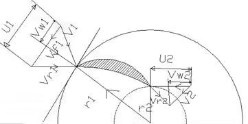
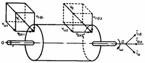
When a fluid passes through a rotor, the absolute velocity vector (V) can be resolved into three orthogonal components: axial (Va), radial (Vr or Vf in some notations) and tangential (Vθ sometimes written as Vw).
Common notation used here:
- V1, V2: absolute velocities at inlet and outlet respectively.
- Va1, Va2: axial components at inlet and outlet.
- Vr1, Vr2 or Vf1, Vf2: radial components at inlet and outlet.
- Vθ1, Vθ2 or Vw1, Vw2: tangential (whirl) components at inlet and outlet; these are the components that contribute directly to torque and shaft work.
- U: blade (peripheral) speed = ω·r.
- W (or Vr in other texts): relative velocity of the fluid as seen from the moving blade; vector relation: V = W + U (vector sum), where U is the blade velocity vector.
Velocity triangles are graphical representations at the rotor inlet and outlet showing vector addition of blade speed (U), relative velocity (W) and absolute velocity (V). They are essential for:
- Determining incidence and flow angles on the blade,
- Designing blade shapes and stagger angles,
- Calculating the tangential components Vθ1 and Vθ2 used in the Euler equation for work.
Notes on components and their effects:
- Axial components (Va) do not directly produce torque but create axial thrust that must be borne by thrust bearings.
- Radial components (Vr or Vf) do not directly produce torque but produce radial forces supported by journal bearings.
- Tangential components (Vθ or Vw) are responsible for the energy transfer between fluid and rotor and appear in the Euler turbine equation.
Practical considerations and losses
Practical turbomachines are affected by many loss mechanisms that reduce performance compared with ideal predictions:
- Profile losses due to blade shape and boundary layer separation.
- Leakage losses through seals and clearances.
- Secondary flows and mixing losses in three-dimensional passages.
- Shock losses in compressible flows and nozzle/guide vane losses.
- Mechanical losses in bearings, seals and gearing.
Design and performance parameters
Important non-dimensional and practical parameters used to compare and select turbomachines include:
- Specific speed (Ns): a dimensionless parameter that relates speed, head and flow and helps to select the appropriate type of turbine or pump for a given application.
- Flow coefficient and head coefficient: non-dimensional groups used in similarity laws and scaling.
- Degree of reaction: fraction of total enthalpy drop occurring in the rotor rather than the stator; important in stage design.
- Model testing and similarity laws: geometric, kinematic and dynamic similarity permit performance prediction from models to prototypes using similarity parameters and Reynolds/Mach number considerations.
Applications and examples
Turbomachines are central to many engineering systems:
- Hydroelectric power plants use Pelton, Francis or Kaplan turbines depending on the site head and discharge.
- Steam and gas turbines drive electrical generators in thermal and combined-cycle power plants.
- Pumps and compressors provide fluid transport and pressurisation in process, HVAC and water supply systems.
- Torque converters and hydraulic couplings transmit power smoothly in vehicle drivetrains and industrial drives.
Summary
Turbomachines transfer energy between a fluid and a rotating element by altering fluid momentum and pressure. The tangential component of fluid velocity controls the shaft work via the Euler turbine equation. Devices are classified by energy transfer, flow direction and hydraulic head. Accurate analysis uses steady-flow thermodynamics, velocity triangles, and assessments of hydraulic and mechanical efficiencies. Practical design balances performance, losses and mechanical constraints to meet application requirements.
FAQs on Turbomachinery- Notes
| 1. What's the difference between impulse turbines and reaction turbines in turbomachinery? |  |
| 2. How do you calculate the specific speed of a turbine and why does it matter? | |
| 3. What causes cavitation in turbines and how can it be prevented? | |
| 4. How do centrifugal pumps work differently from axial flow pumps in turbomachinery applications? | |
| 5. What is the Euler turbine equation and how does it apply to real turbomachinery design? | |


