Oscillators - 2


Oscillators with LC Feedback Circuits
Although RC feedback oscillators such as the Wien bridge are generally suitable for frequencies up to about 1 MHz, LC feedback elements are normally used where higher frequencies of oscillation are required. Because many operational amplifiers have limited unity-gain frequency, discrete active devices (BJT or FET) are commonly used as the gain element in LC oscillators. This section introduces several resonant LC feedback oscillators - the Colpitts, Clapp, Hartley, Armstrong - and crystal-controlled oscillators, followed by a discussion of relaxation oscillators and linear wave-shaping circuits.
The Hartley Oscillator
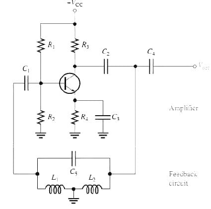
The Hartley oscillator is a resonant LC feedback oscillator in which the frequency-determining network consists of two inductors in series with a parallel capacitor. The voltage feedback is taken from a tap between the inductors so that the divided inductance provides the feedback fraction.
The frequency of oscillation (for sufficiently high tank quality factor, Q > 10) is determined by the effective inductance and the capacitor:
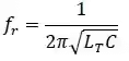
where LT = L1 + L2.
- The two series inductors play a role analogous to the two capacitors C1 and C2 in the Colpitts oscillator: they determine the feedback attenuation B of the network.
- The feedback fraction is B = L1/L2.
- To assure start-up of oscillation, the loop gain must satisfy the Barkhausen criterion; the amplifier voltage gain magnitude must exceed the reciprocal of the feedback attenuation: Av > 1/B. For the simple tapped-inductor Hartley, the required amplifier gain can be written as Av = L2/L1 in the idealised lossless case.
- Loading of the tank circuit by the active device or by external circuitry reduces the effective Q of the tank and consequently lowers the oscillation frequency and increases amplitude distortion.
The Colpitts and Clapp Oscillators
The Colpitts oscillator uses a single inductor in parallel with a series combination of two capacitors (C1 and C2) as the resonant tank. The capacitors form a voltage divider that provides the required feedback to the amplifier input. The effective capacitance seen by the inductor is the series combination of the two capacitors:
- Ceq = (C1 C2) / (C1 + C2).
- The oscillation frequency is approximately f ≈ 1 / [2π √(L Ceq)] for high Q.
- The feedback fraction is set by C1 and C2; to start oscillation the amplifier gain must exceed the reciprocal of the capacitor divider ratio.
- Colpitts oscillators are widely used at VHF and UHF frequencies because they can provide good frequency stability and low phase noise when built with appropriate components.
The Clapp oscillator is a practical modification of the Colpitts in which an extra small capacitor is placed in series with the inductor. This series capacitor (often called Cc) dominates the effective capacitance, making the oscillation frequency less sensitive to the transistor or stray capacitances and improving frequency stability. The effective capacitance in the Clapp circuit is the series combination of C1, C2 and Cc, and the approximate frequency is f ≈ 1 / [2π √(L Ceff)], where Ceff is the net series capacitance. Clapp oscillators are preferred where improved stability is needed at higher frequencies.
The Armstrong Oscillator
The Armstrong oscillator uses transformer coupling to return a portion of the output voltage to the input. A portion of the tank circuit voltage is taken from a secondary coil (or tap) and fed back to the active device input. Transformer coupling provides galvanic isolation and a convenient way to obtain the desired feedback phase and magnitude, but transformers add size and cost, which makes Armstrong less common in modern compact designs.
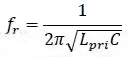
The frequency of oscillation is set by the inductance of the primary winding Lpri together with the capacitor C1 connected across it.
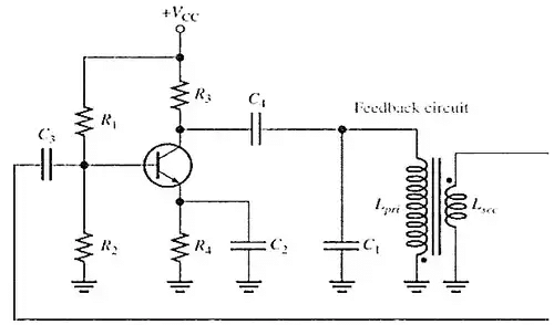
- The secondary winding provides the required feedback voltage; its turns ratio determines the feedback fraction.
- Because of transformer leakage inductance and winding parasitics, careful design is required to obtain stable oscillation at high frequencies.
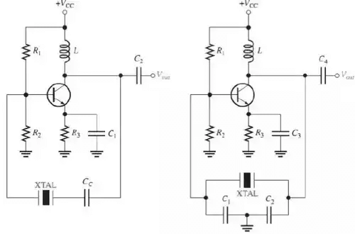
Crystal-Controlled Oscillators
For the most stable and accurate frequency sources, a piezoelectric crystal (typically quartz) is used as the frequency-determining element in the feedback loop. Crystal oscillators combine excellent frequency stability with low phase noise and are widely used in clocks, radio transmitters and receivers, and digital systems.
The Piezoelectric Effect and Crystal Equivalent Circuit
- Quartz is a crystalline material that exhibits the piezoelectric effect: mechanical stress produces an electrical voltage, and conversely an applied voltage produces mechanical deformation (vibration).
- When an AC voltage is applied across a crystal it vibrates at the drive frequency; the vibration amplitude is largest at the crystal's natural mechanical resonant frequency, which depends on the crystal's physical dimensions and the orientation in which it is cut.
- The crystal can be represented by an electrical equivalent comprising a series branch of motional inductance, motional capacitance and motional resistance (representing the mechanical resonance) in parallel with a static capacitance C0 (the holder and electrode capacitance). Because of this, the crystal exhibits both series resonance and parallel (anti-resonance) behaviour.
- The impedance of the crystal is minimum at the series resonant frequency and is maximum at the parallel resonant frequency.
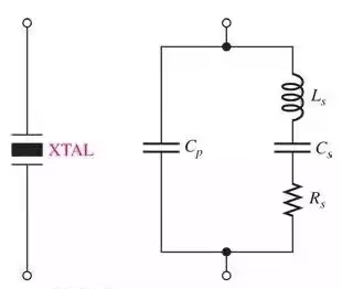
At series resonance the crystal behaves like a low impedance which can provide maximum feedback; at parallel resonance it behaves like a high impedance causing maximum voltage build-up across capacitors in the network. A small tuning capacitor Cc (often in series) is frequently used to fine-tune the oscillator frequency by slightly changing the overall reactance seen by the crystal.
- In crystal oscillators the active device provides the required gain while the crystal enforces a very stable frequency due to its high Q.
- Crystal-controlled oscillators can operate either at the series resonant frequency or at a parallel (near-resonant) mode depending on the circuit topology and loading.
Relaxation Oscillators
The second major category of oscillators is the relaxation oscillator. These generate periodic waveforms using an RC timing circuit together with a nonlinear device or switching element that changes state once thresholds are reached. Relaxation oscillators typically produce square, triangular or sawtooth waveforms rather than sinusoidal outputs.
Triangular-Wave Oscillator
An operational-amplifier integrator can form the core of a triangular-wave generator when combined with a switching element that reverses the integrator input polarity at fixed intervals. The integrator converts a constant input voltage into a linear ramp (triangle) output.
- When the switch applies a constant positive input to the integrator, the output ramps linearly in one direction (positive slope).
- When the switch applies the opposite polarity, the integrator output ramps linearly in the other direction (negative slope).
- Alternating the switch position at appropriate thresholds produces a continuous triangular waveform made of alternating positive-going and negative-going ramps.
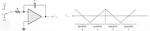
Triangular generators are used where a linear ramp is required, for example in waveform synthesis, function generators, and sweep circuits.
Square-Wave Oscillator
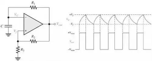
A common square-wave relaxation oscillator uses an op-amp or comparator with positive feedback to create hysteresis (a Schmitt trigger) and an RC network to provide timing. The comparator output swings to its positive or negative saturation limits, forcing the capacitor to charge or discharge toward those output rails through a resistor.
- Initially the capacitor voltage is at some value (often 0 V when powered up); the comparator output will saturate to one extreme, causing the capacitor to charge through the resistor toward that extreme.
- When the capacitor voltage reaches the threshold set by the feedback network on the non-inverting input, the comparator switches to the opposite saturation level.
- The capacitor then discharges (or charges toward the opposite rail) until it reaches the opposite threshold, and the comparator switches back. This repeating action produces a square-wave output.
- The non-inverting input fraction of the output (set by resistors R2 and R3) provides hysteresis which defines the switching thresholds and therefore the duty cycle and frequency together with R1 and the capacitor.
Linear Wave-Shaping Circuits
The process by which the form of a non-sinusoidal signal is altered by transmission through a linear network is called linear wave-shaping. Linear networks do not introduce frequency components not present in the input; instead they attenuate or phase-shift frequency components according to their transfer function. Two basic first-order RC networks often used for wave-shaping are the RC low-pass and RC high-pass circuits.
RC Low-Pass Circuit
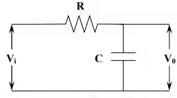
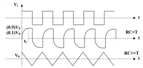
An RC low-pass circuit passes low frequencies with little attenuation while attenuating higher frequencies because the capacitor reactance decreases with increasing frequency. At very high frequencies the capacitor behaves like a short circuit and the output tends toward zero.
When driven by a signal whose period T is much less than the RC time constant (that is, if RC ≫ T), the circuit acts approximately as an integrator: the output voltage is proportional to the time integral of the input voltage over each interval of interest. This property is used to convert square waves to approximate triangular waves, to recover pulse area information, or to perform low-frequency filtering.
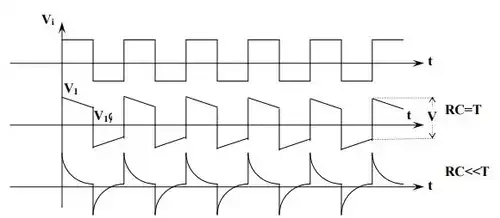
RC High-Pass Circuit
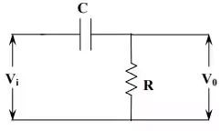
An RC high-pass circuit passes higher frequency components with less attenuation than lower frequency components because the capacitor reactance decreases as frequency increases. At very low frequencies the capacitor blocks the signal and the output tends to zero.
When the RC time constant is much smaller than the period of the input signal (that is, if RC ≪ T), the circuit operates approximately as a differentiator: the output voltage is proportional to the time derivative of the input voltage. This behaviour is useful for detecting rapid transitions (edges), emphasising high-frequency components, and pulse shaping.
Applications and Design Considerations
- Colpitts/Clapp - widely used for RF oscillators where compactness and good frequency stability are needed; Clapp is preferred when improved frequency stability is required.
- Hartley - used where a tapped inductor is convenient; often used in tuned RF oscillators when inductors are readily available.
- Armstrong - historically important where transformer coupling was required; less common now due to size and cost of transformers.
- Crystal oscillators - chosen where high frequency accuracy and stability are essential (clocks, communication systems, microcontroller crystals).
- Relaxation oscillators - useful for simple waveform generation (square, triangle), timing and clock circuits at low to moderate frequencies.
- Design considerations for LC oscillators include loading effects on the tank (Q reduction), component tolerances, stray capacitances and inductances, temperature stability, and phase noise.
Summary
LC feedback oscillators provide efficient means to generate high-frequency sinusoidal signals; different topologies (Colpitts, Clapp, Hartley, Armstrong) trade off complexity, component sensitivity and stability. Crystal oscillators provide the highest frequency stability using the piezoelectric effect of quartz. Relaxation oscillators generate non-sinusoidal periodic waveforms using RC timing and switching elements. Linear RC networks (low-pass and high-pass) are fundamental tools for wave-shaping, acting as integrators or differentiators under appropriate time-constant conditions.


 | Explore Courses for Electronics and Communication Engineering (ECE) exam |
 | Get EduRev Notes directly in your Google search |